Build#
Welcome to the build guide for Micronova's DIY kit. We hope you have a great time putting your Micronova together and a wonderful time using it.
Please read all instructions thoroughly before starting. If you have questions or run into trouble please reach out to us on discord or drop us an email.
Some soldering experience is helpful but not required. If it's your first time soldering we recommend reading through Adafruit's guide to excellent soldering.
This is a beginner level kit. Some soldering experience is helpful but not required, though we recommend practicing on another project first. We also have some slightly easier kits available, such as our Helium kit. Even if you've got some experience, we recommend taking a look at Adafruit's guide to excellent soldering.
This build takes around one hour to complete.
Tools required#
Before you begin, make sure that you've got:
- Safety glasses. Yes, really. A pair like these are fine.
- Proper ventilation, like this small filtered fan.
- A temperature-controlled soldering iron, like this Hakko or the Pinecil. It is very important to use a temperature-controlled iron, since unregulated irons can easily get hot enough to damage components. You should set your iron temperature based on your solder manufacturer's recommendations.
- Solder. We recommend Adafruit's SAC305 solder or Kester 275 K100LD.
- A small flat head screwdriver, like [this one][small screwdriver].
Flux
We suggest using solder with "no clean" flux. If you use a different kind of flux, be sure to carefully clean the flux residue off based on the guidelines provided by the manufacturer of your solder. Take special care with the LEDs and potentiometers, as they can be damaged by water and flux cleaners.
Kit contents#
Your kit should contain the following items. If any are missing please email us at support@winterbloom.com.
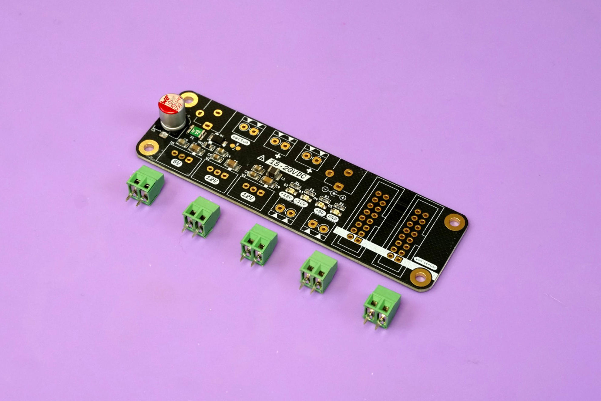
- (1) Mainboard
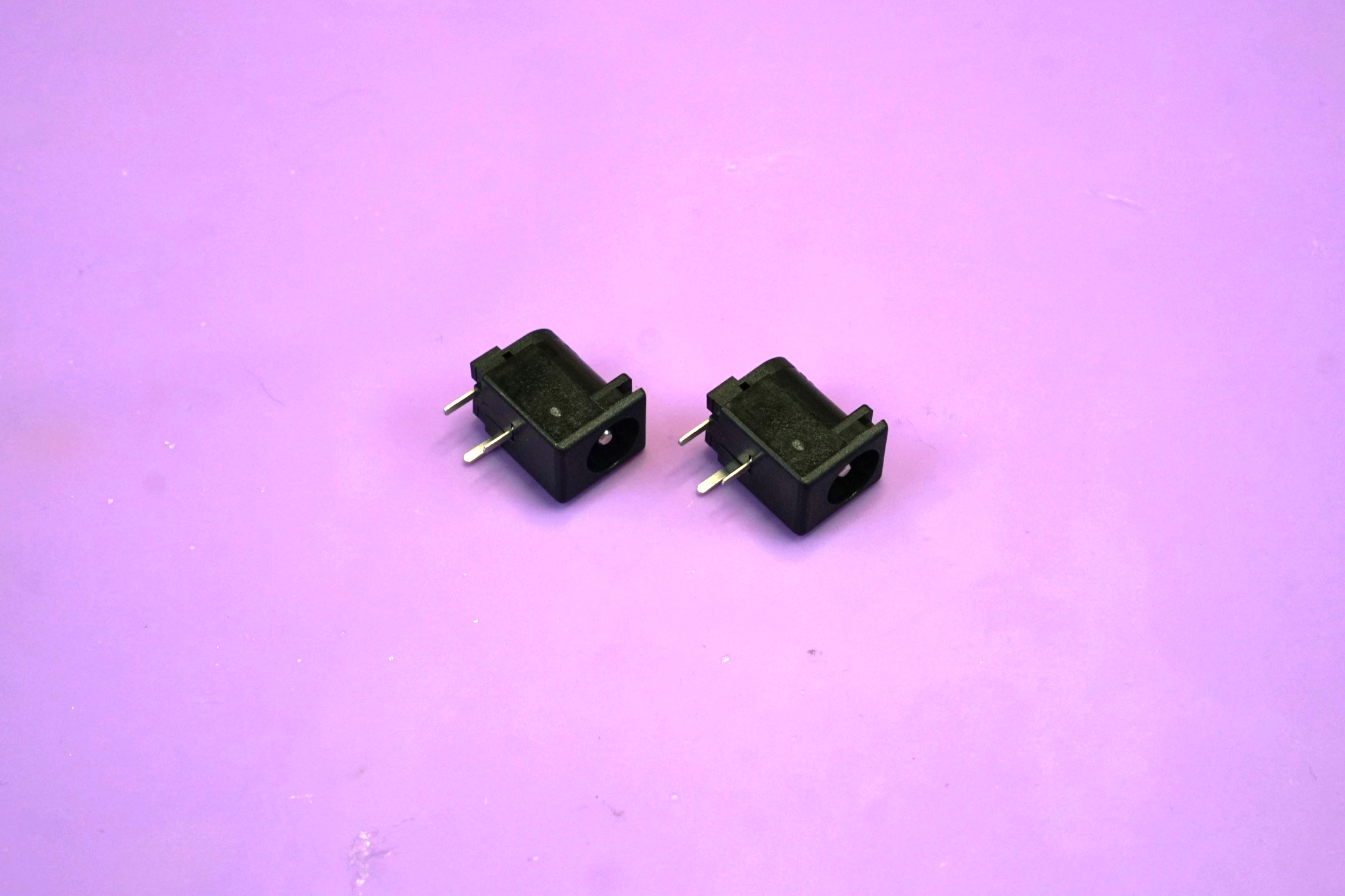
- (2) DC barrel jacks
- (5) 2-pin screw terminal blocks
- (2) 16 pin shielded IDC headers
- (2) 12V DC-DC converters
- (1) 5V DC-DC converter
Screw terminals#
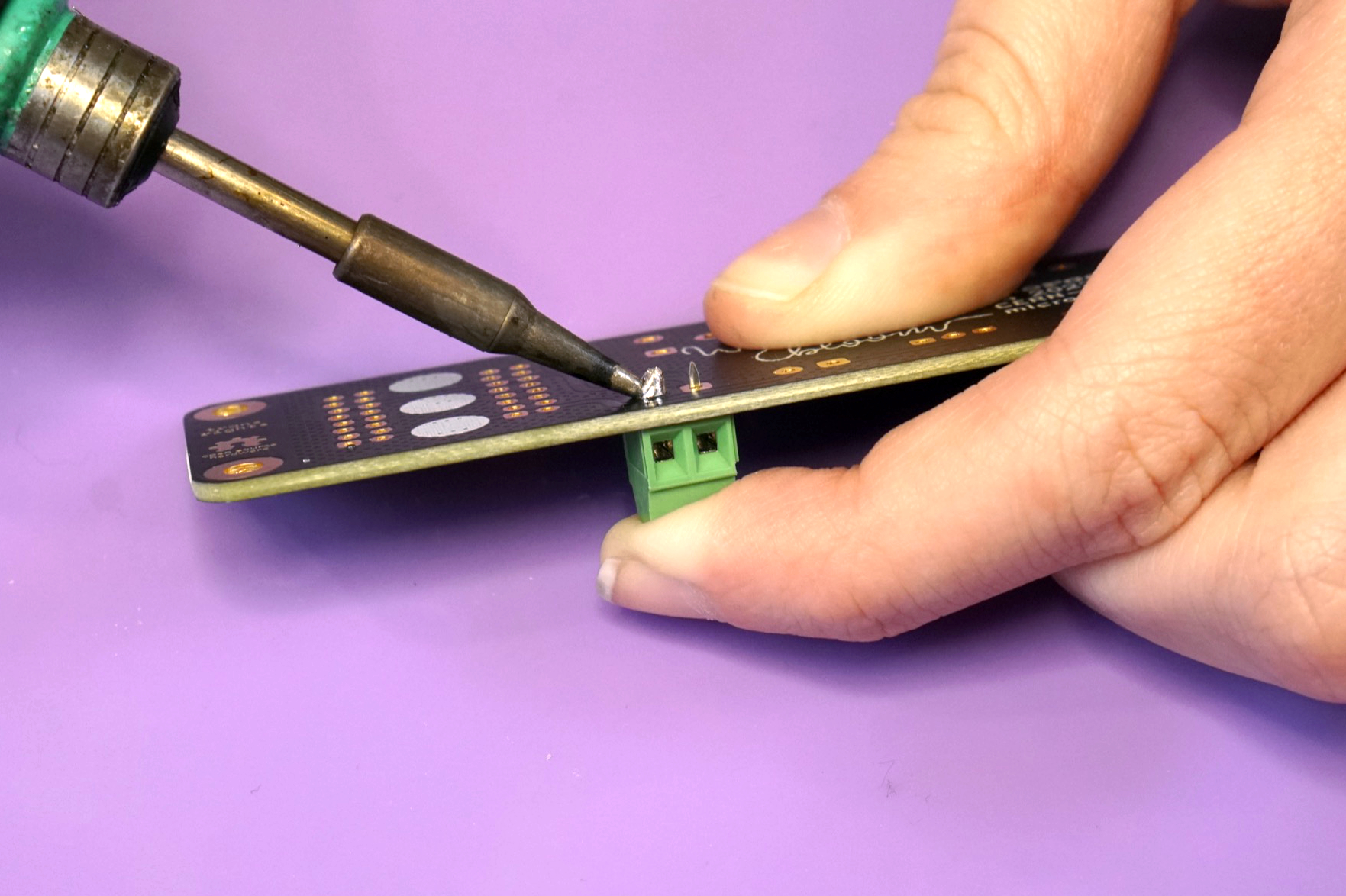
The first step is placing and soldering the five 2-pin screw terminal blocks.
It's easiest to solder one terminal block at a time. Place a terminal block on the front side of the board, taking care to place it so that the terminal openings face outward and match up with the triangles on the board.
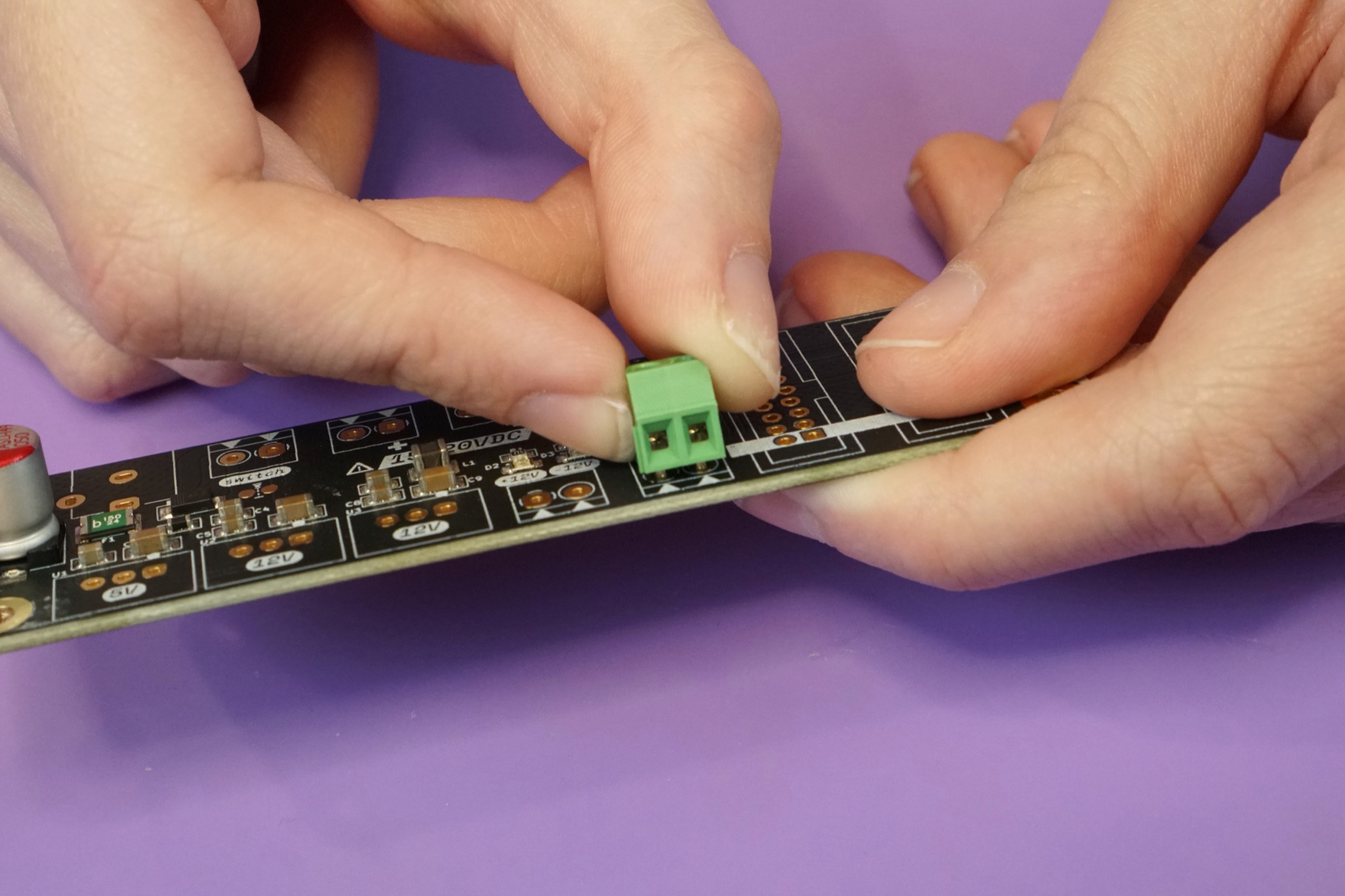
Hold the terminal block in place and flip the board over. It's okay if the terminal block isn't completely flush against the board, as long as the legs are through the holes.
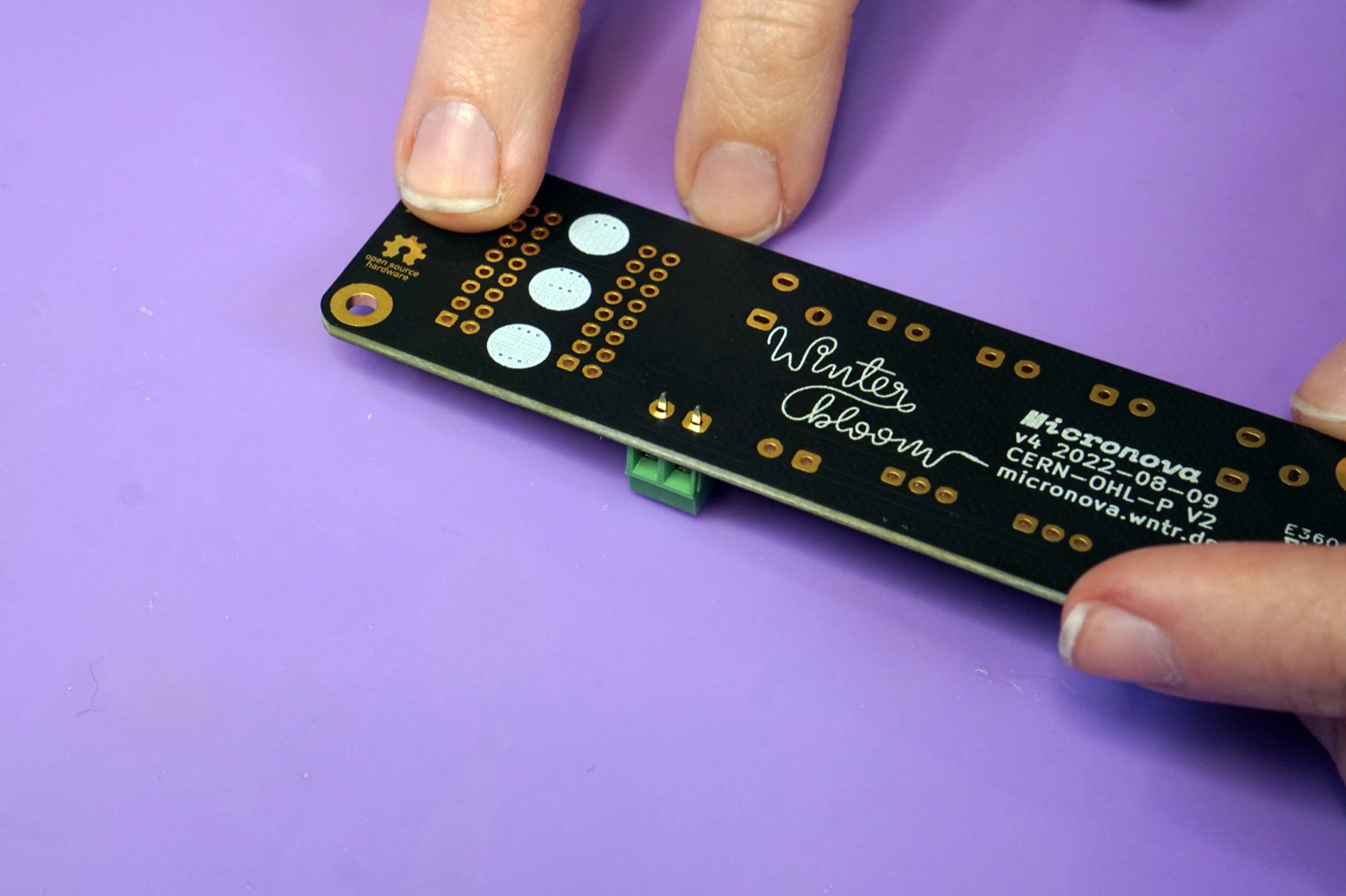
Solder one leg of the terminal block to hold it in place.
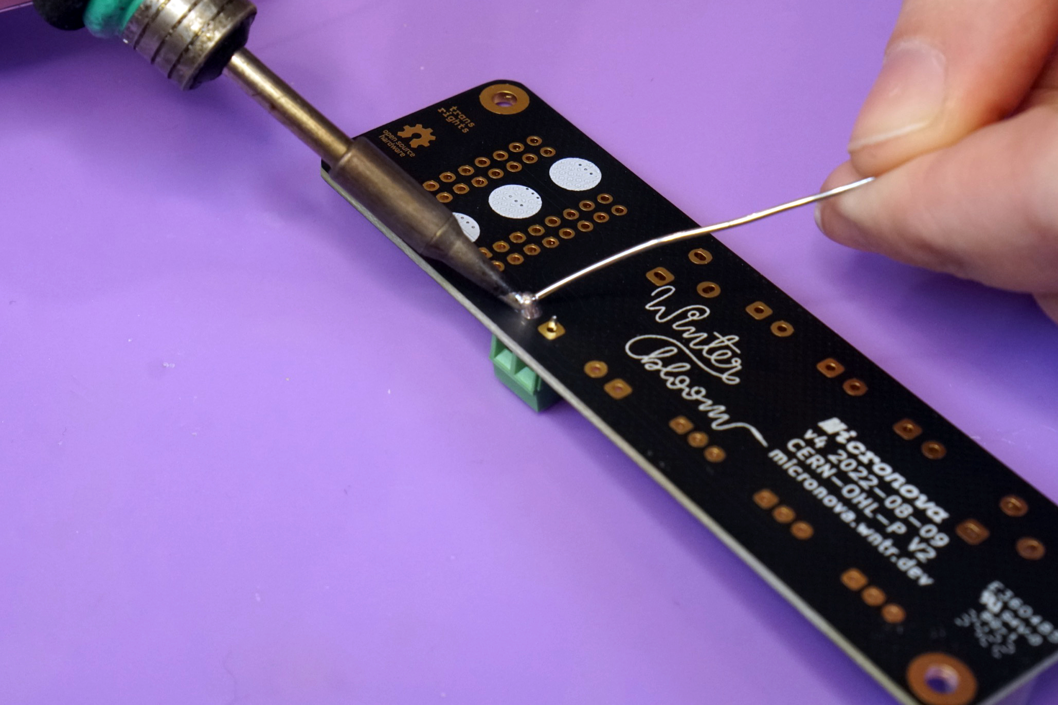
Lift the board and use your iron to reflow the solder and push the terminal block flush against the board. Wait a few seconds for the joint to solidify before releasing the board.
With the terminal block now flush against the board, solder the second leg into place.
Repeat this process for the four remaining terminal blocks, taking care to align the terminal openings.
IDC headers#
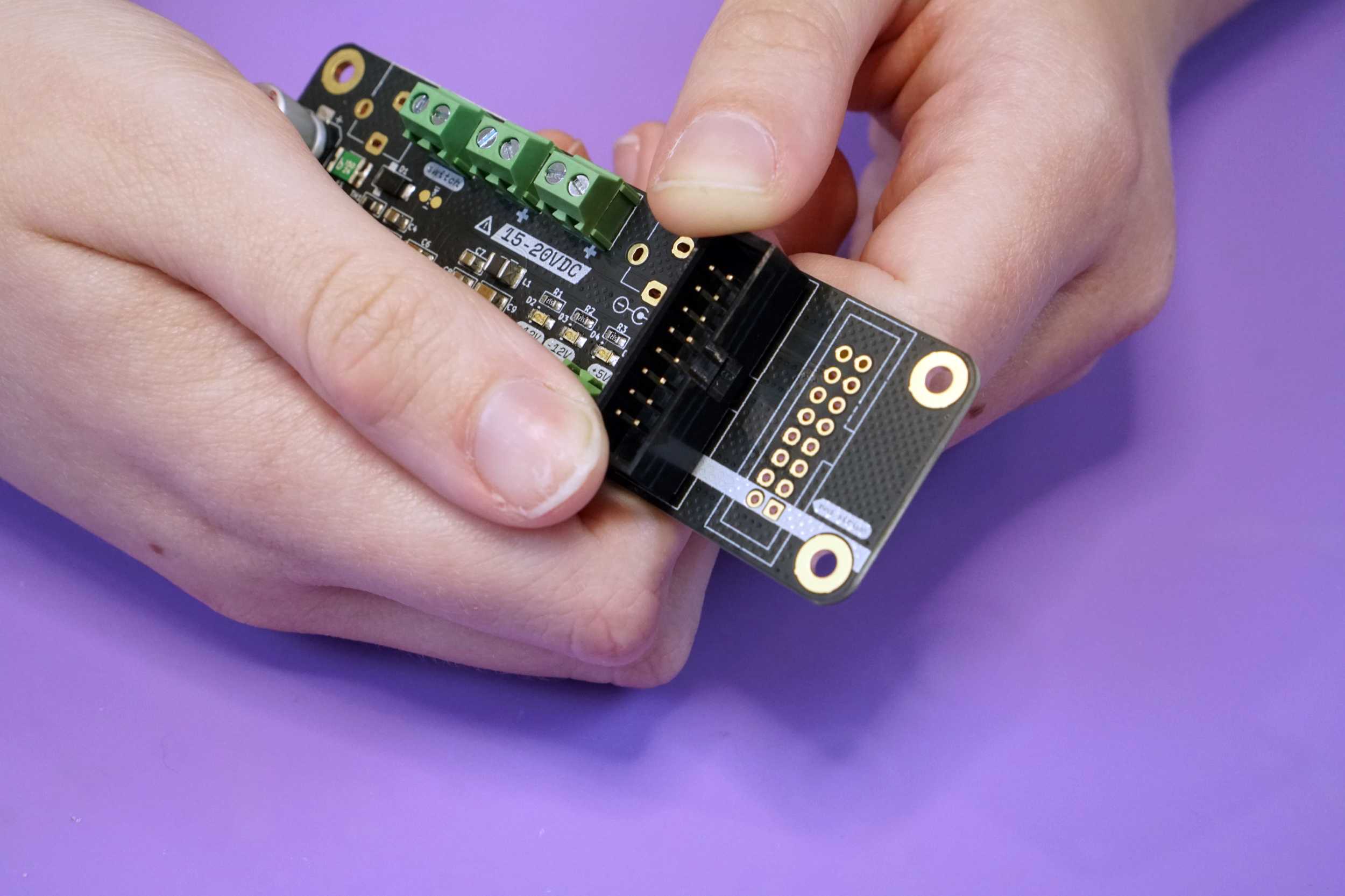
Your next task is placing and soldering the two 16 pin shielded IDC headers.
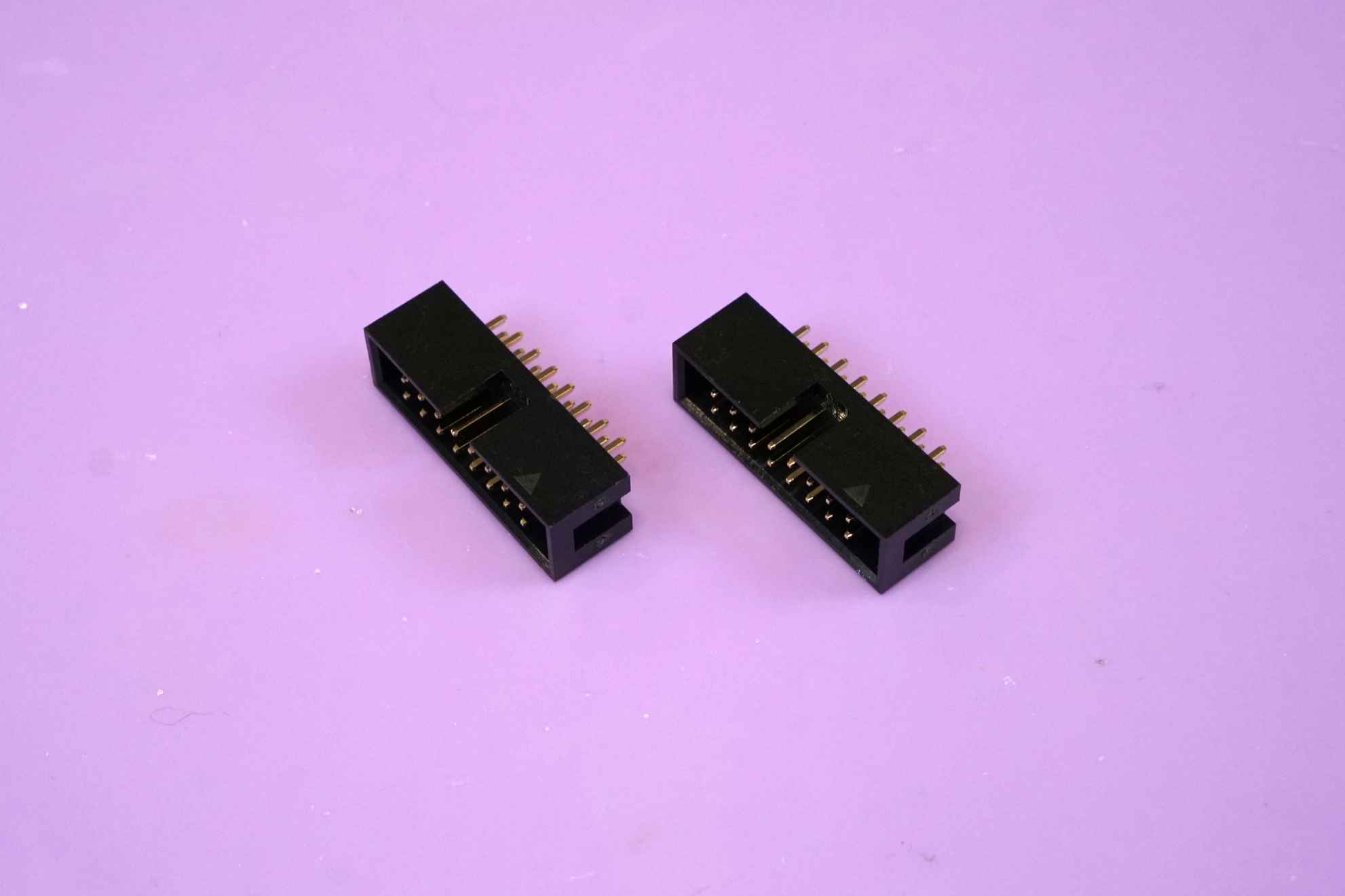
Place both of them on the front side of the board, being careful to align the notch in the header's shield with the drawing on the board. The board is designed to hold on to these headers tightly, so you might have to give a little pressure to push them all the way in.
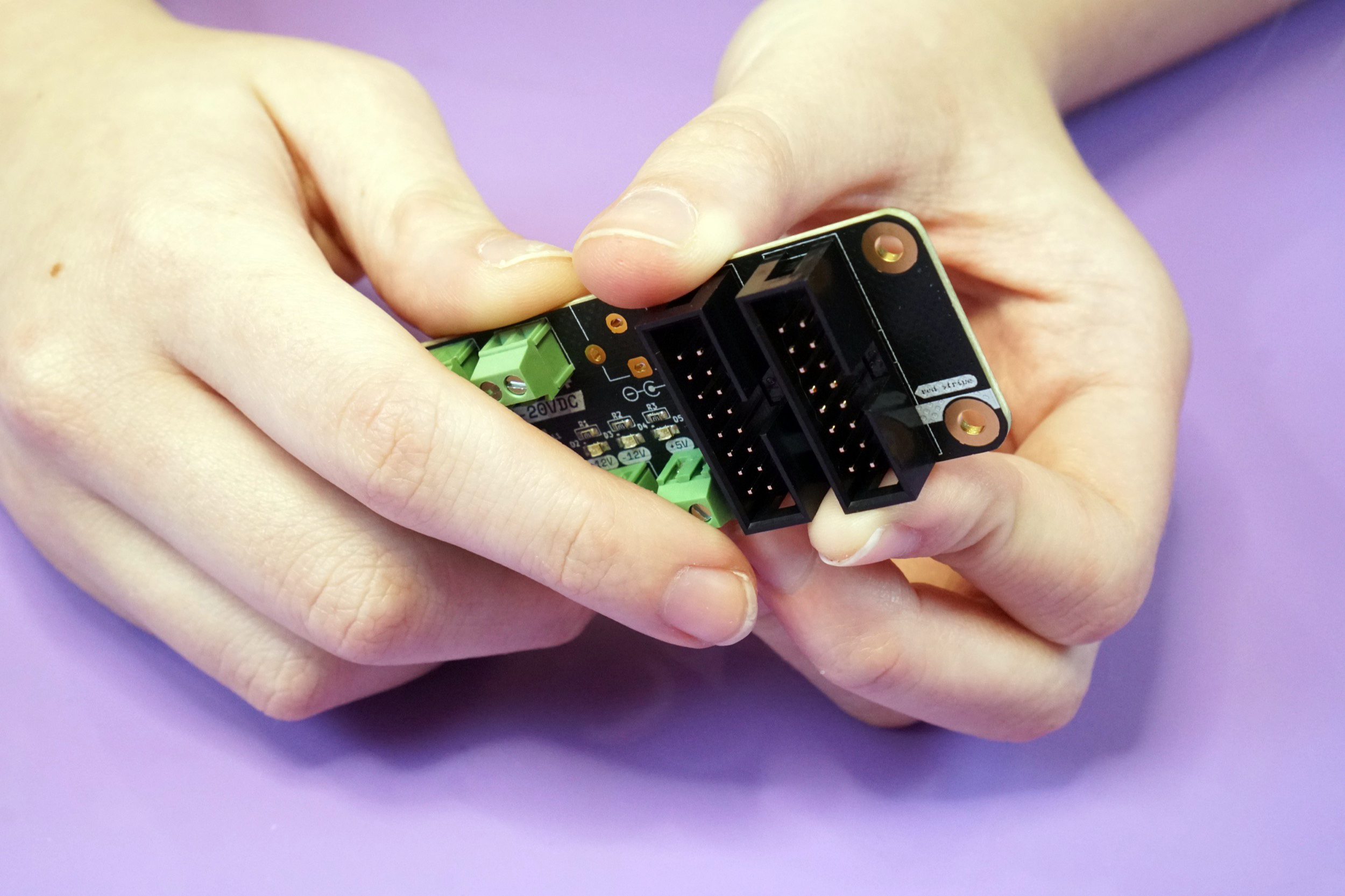
Once you have both placed, flip the board over and solder just one pin on each header to tack it in place.
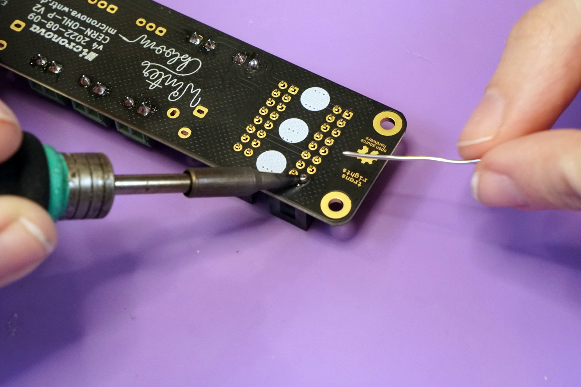
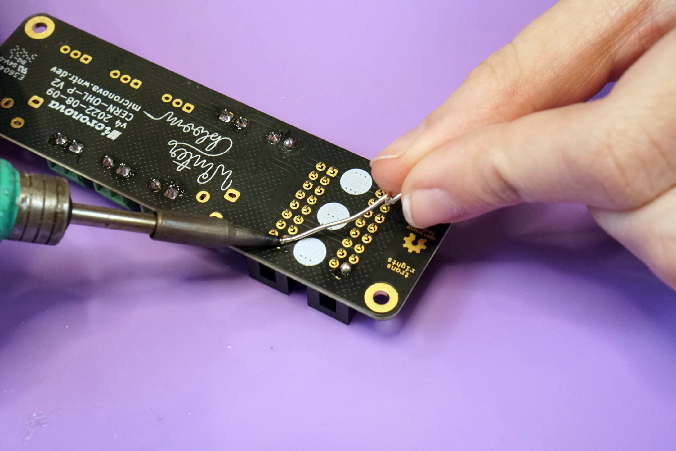
Double check that both headers are completely flush against the board, if they aren't, you can fix them using the same technique you used with the screw terminals. Once you've checked the placement, solder all 16 pins on both headers. You should be able to do them both at the same time, but if you're having trouble feel free to do them one at a time like you did with the terminal blocks.
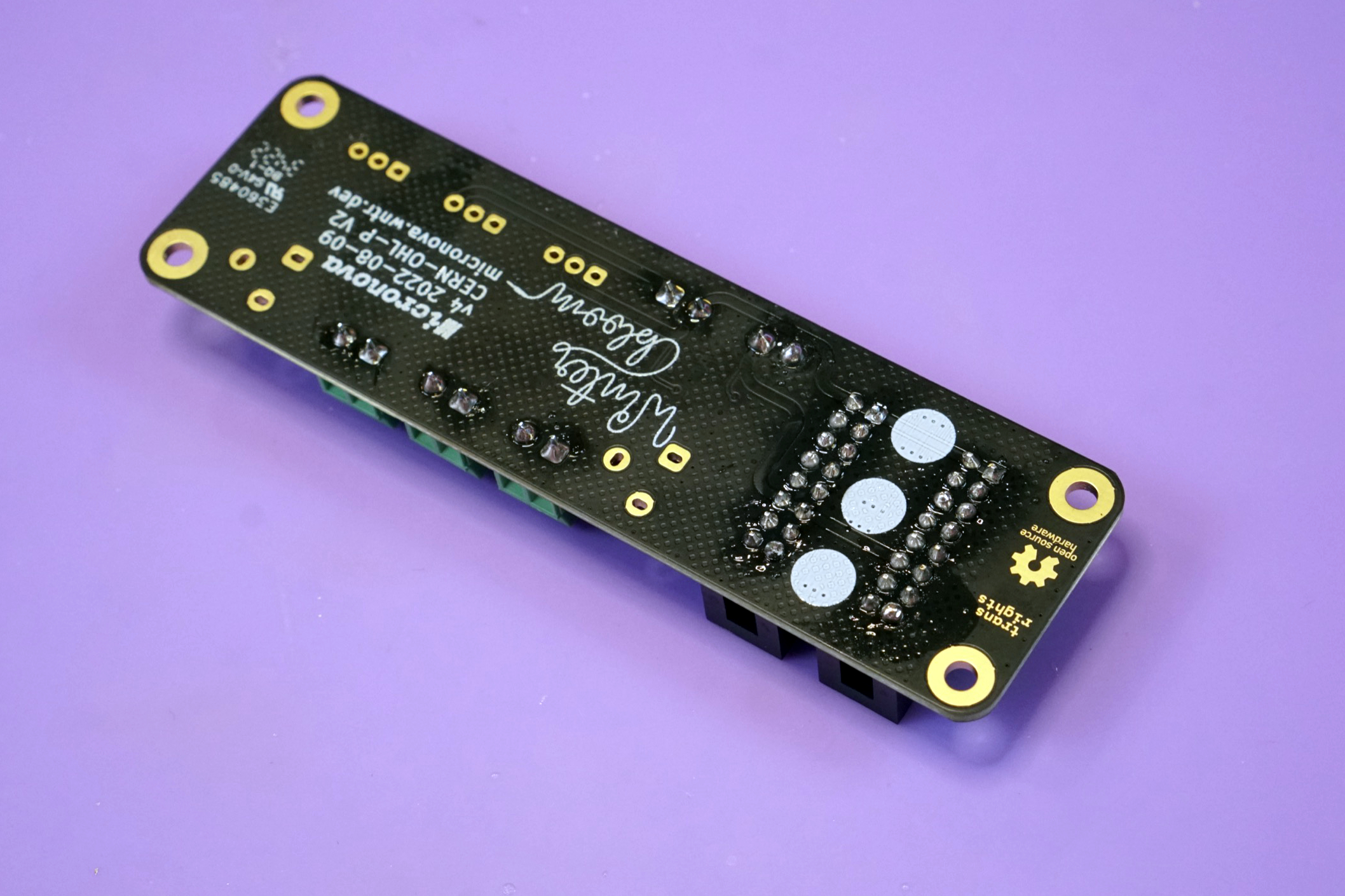
DC barrel jacks#
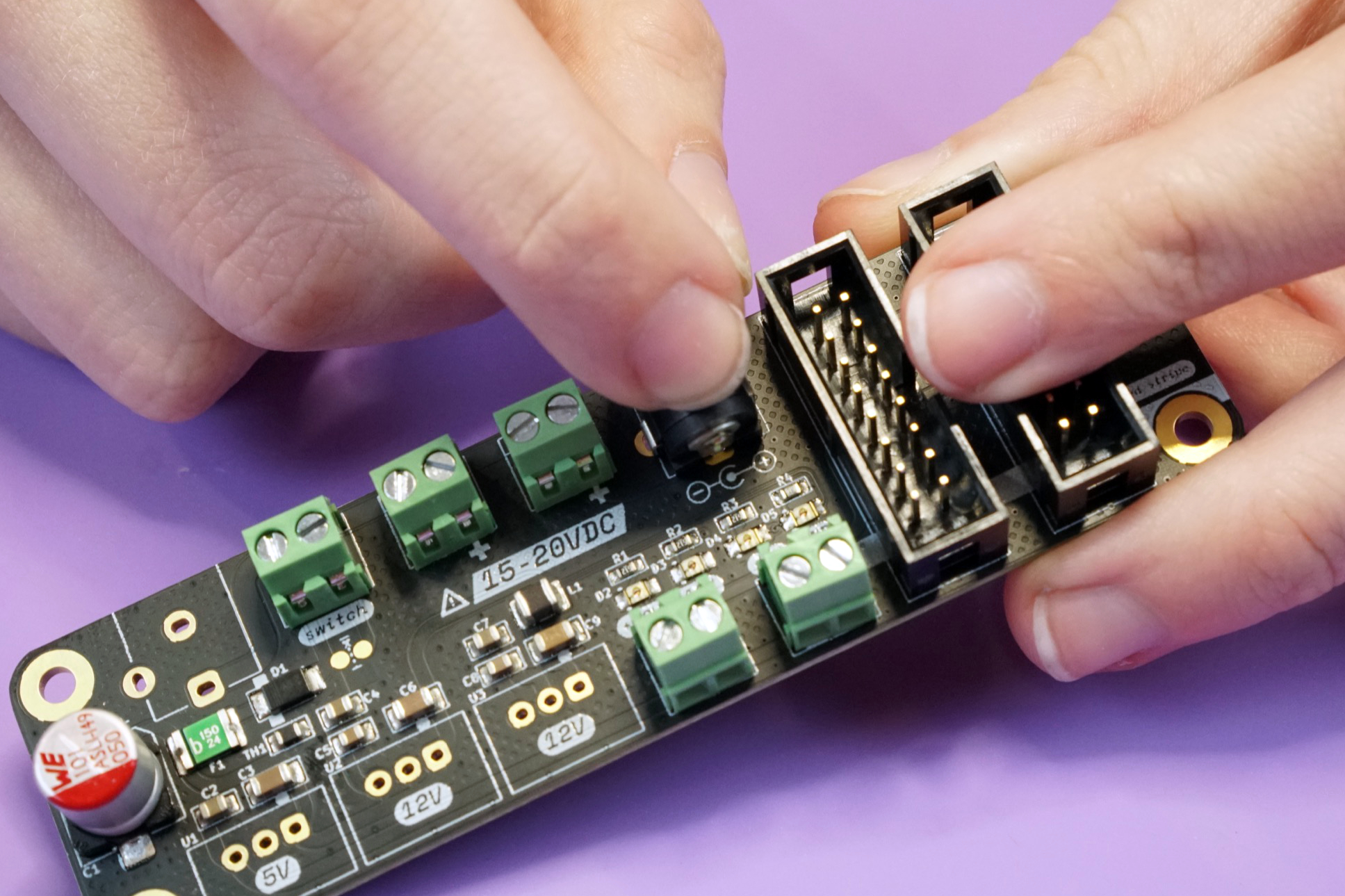
Next up is placing and soldering the two DC barrel jacks.
Similar to the terminal blocks, it's easiest to place these one at a time. Place one on the front side.
Then carefully flip the board over and solder just one leg to hold the barrel jack in place.
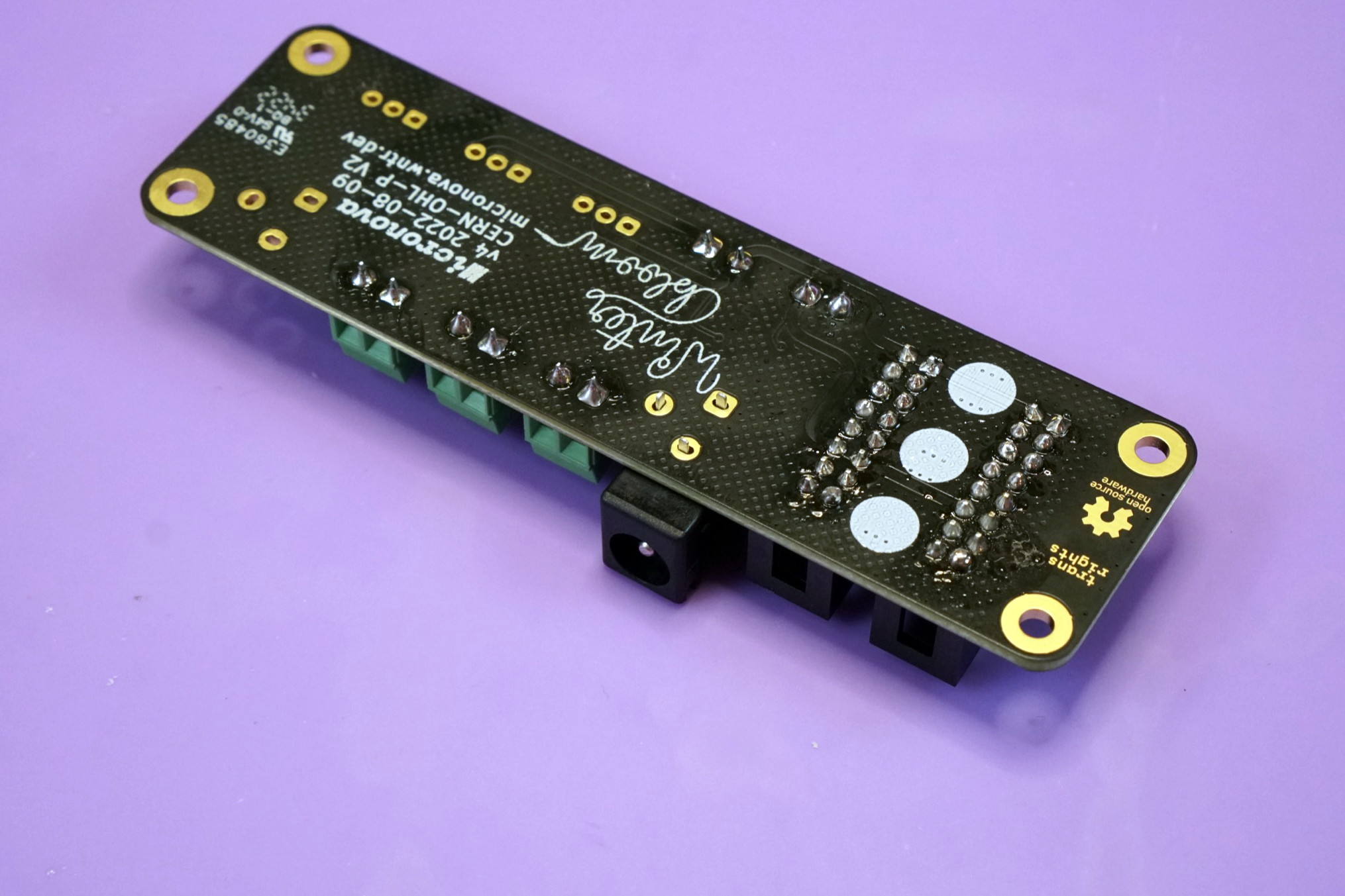
Just as you did with the terminal blocks, lift the board and use your iron to reflow the solder and push the barrel jack flush against the board. Wait a few seconds for the joint to solidify before releasing the board.
With the barrel jack flush and held in place, solder the remaining two legs.
Finally, repeat this process for the second barrel jack.
DC-DC converters#
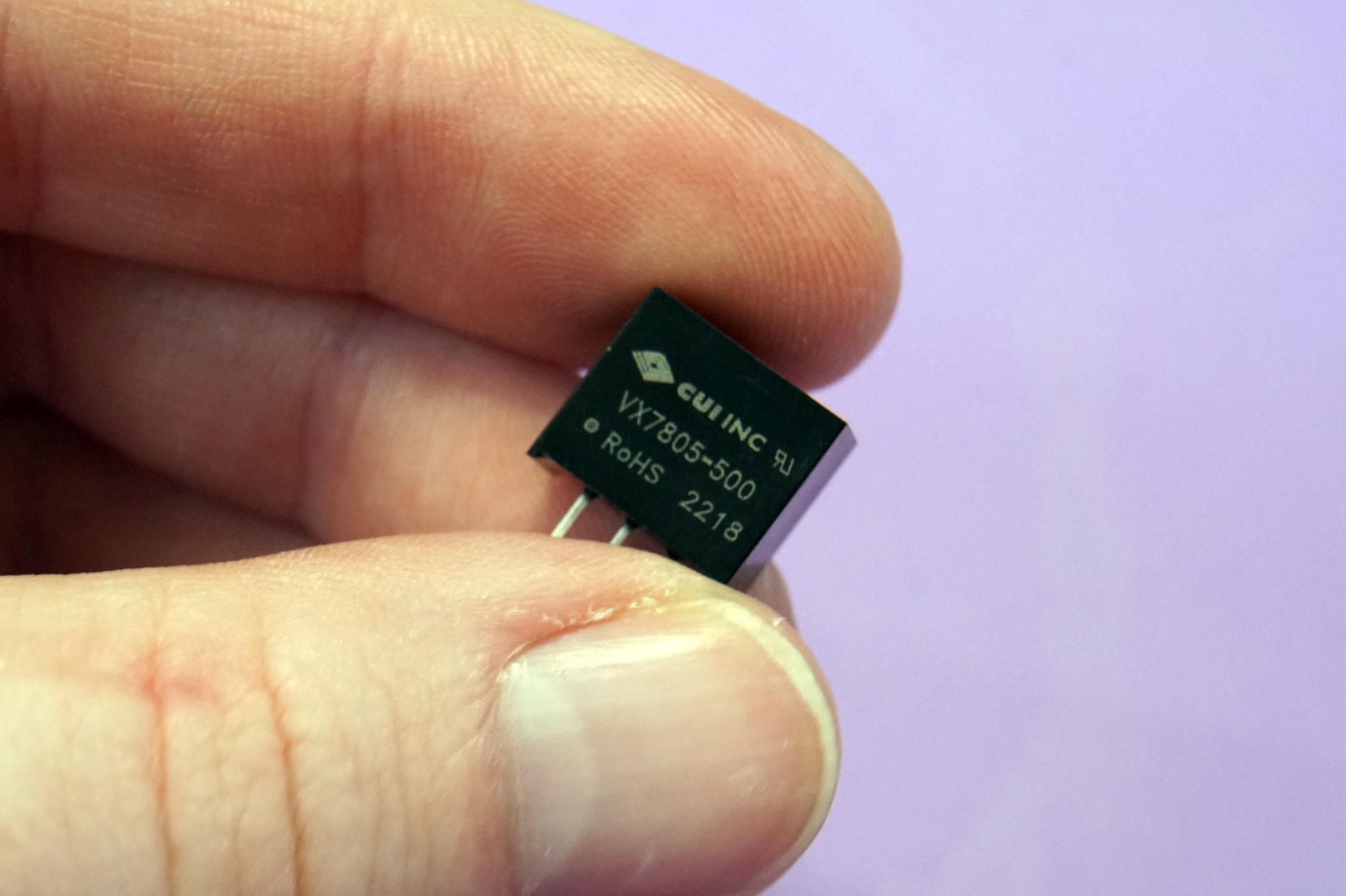
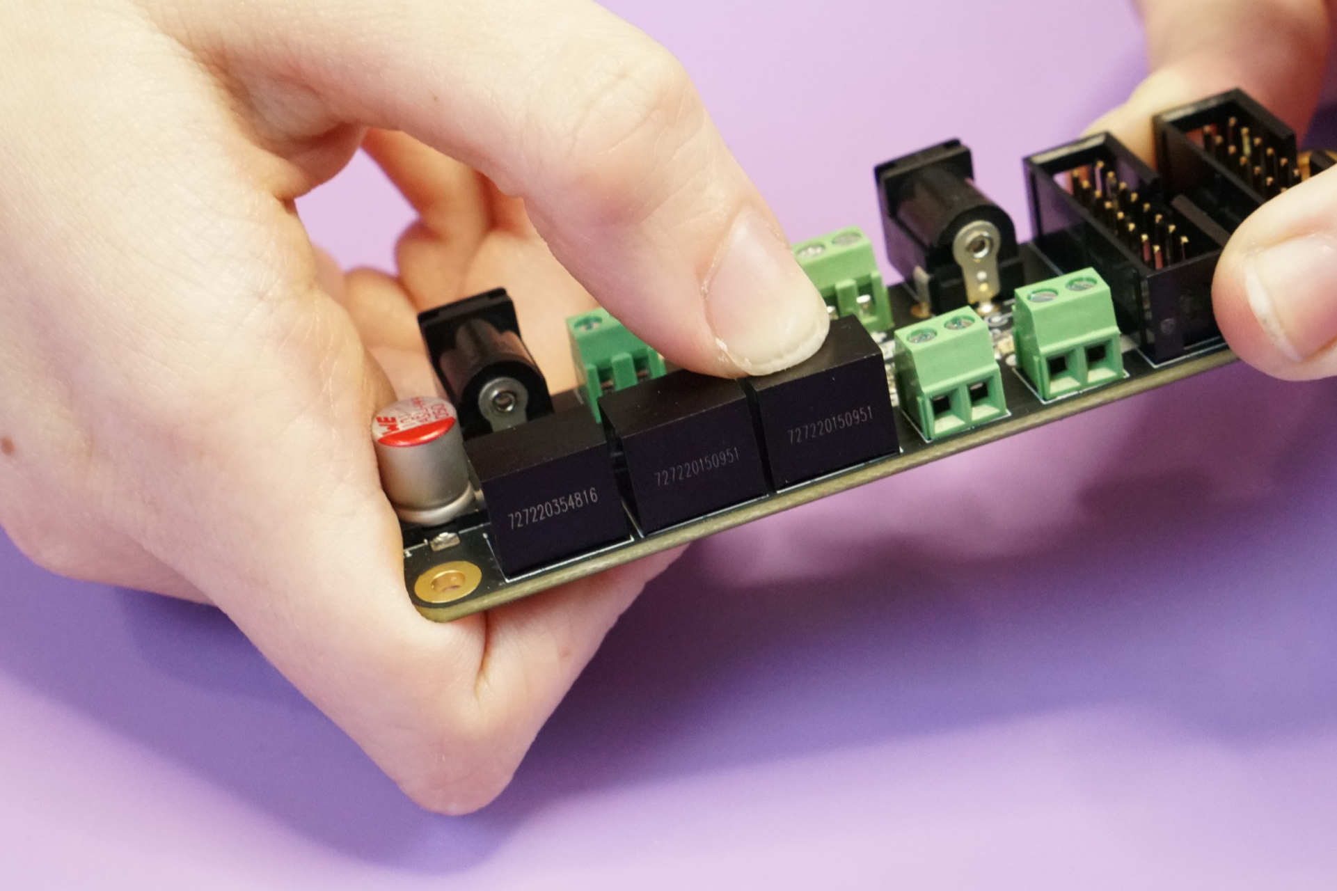
The last step is to solder the three DC-DC converters. There are two 12V converters and one 5V converter. You'll need to identify them before placing them since they must be placed correctly for Micronova to work.
The single 5V converter is slightly smaller and has VX7805-500 marked on it.
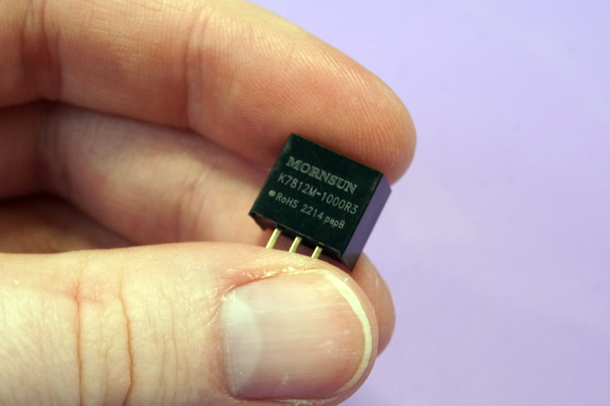
The two 12V converters are slightly larger and has K7812M-1000R3 marked on it.
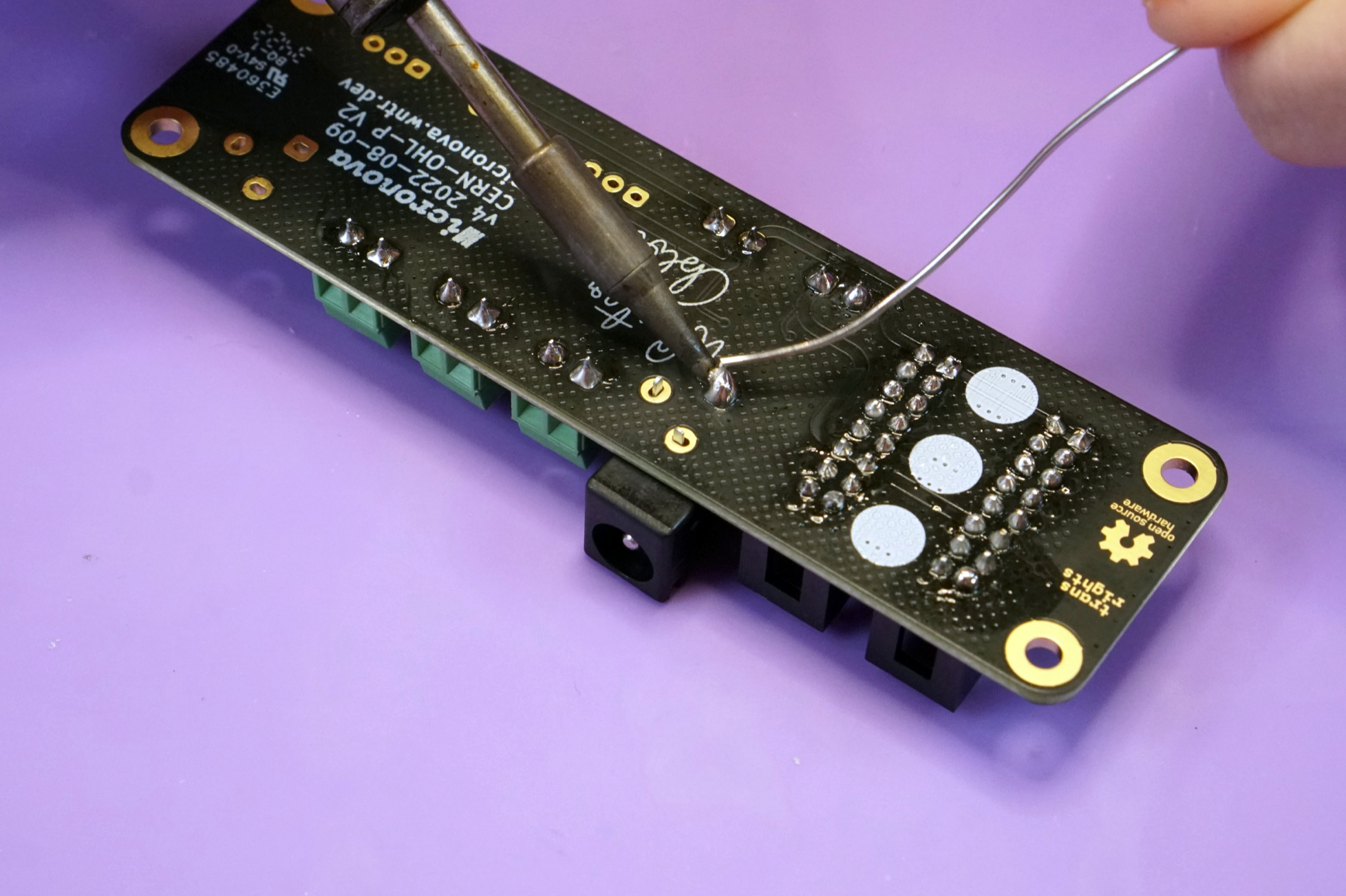
Start by placing the 5V converter on the front side of the board. It goes in the spot labeled 5V on the lower left. Make sure the converter is oriented correctly so that it fits nicely within the white rectangle on the board.
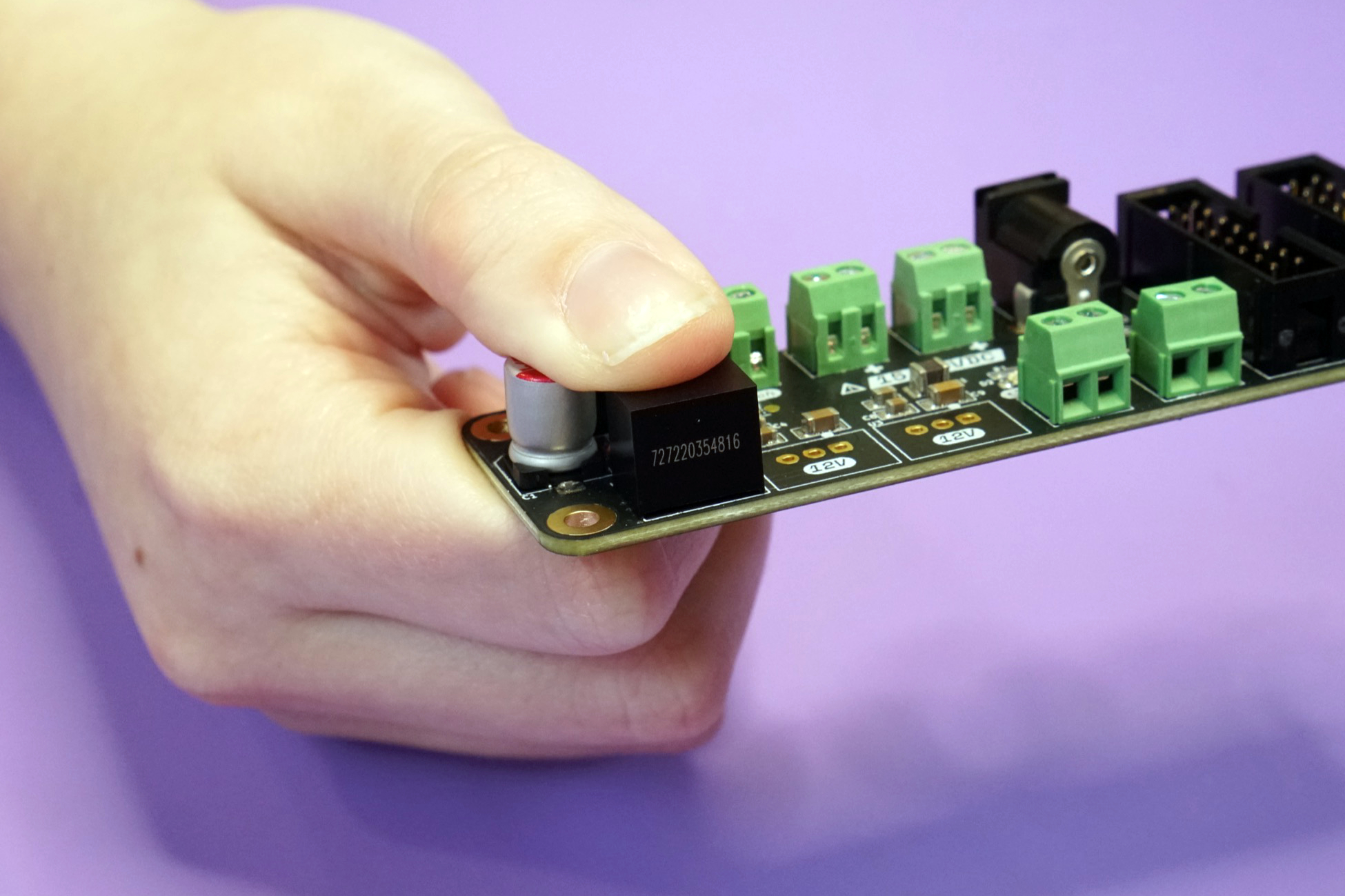
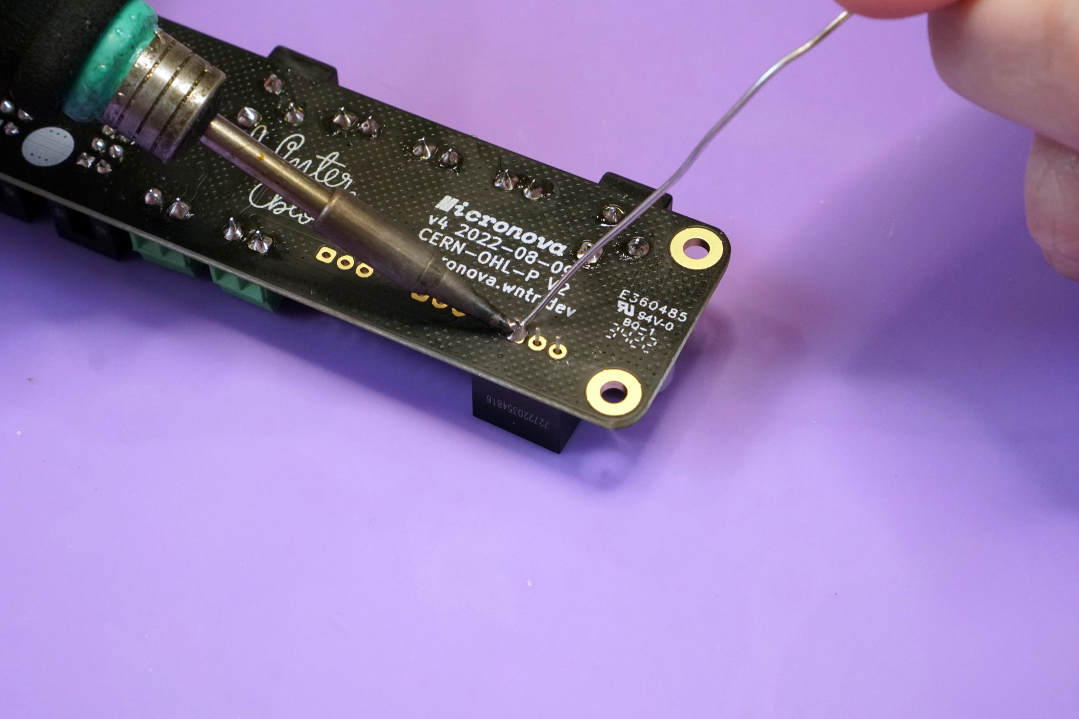
Carefully flip the board over and solder one leg to hold the converter in place.
Using the same technique as the DC barrel jacks and terminal blocks, reflow the solder and push the DC-DC converter flush against the board.
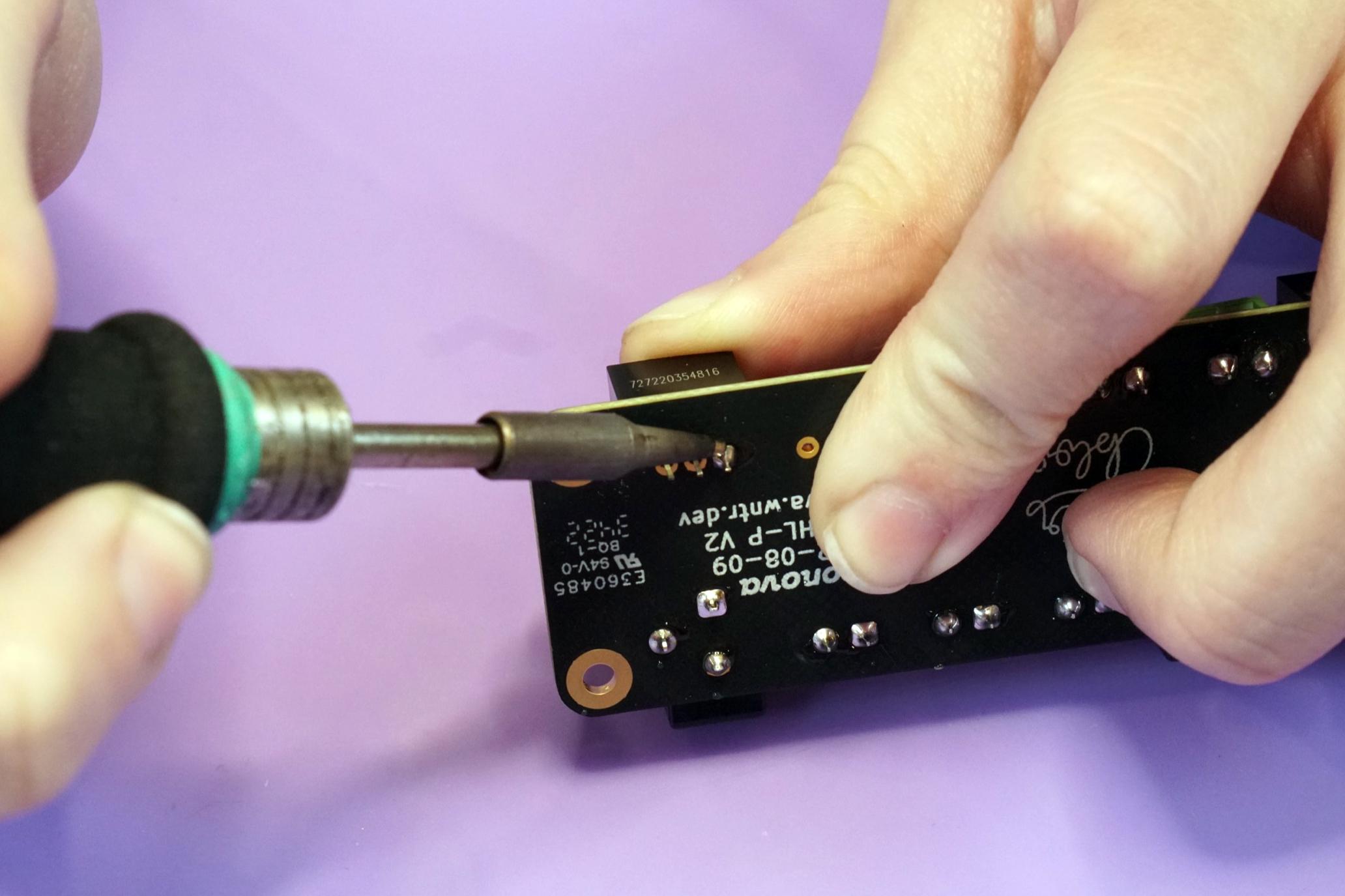
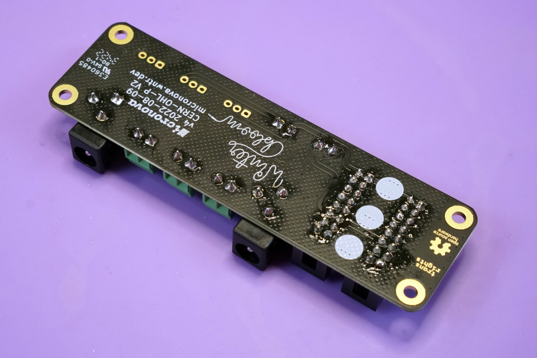
Once the DC-DC converter is flush, solder the remaining legs.
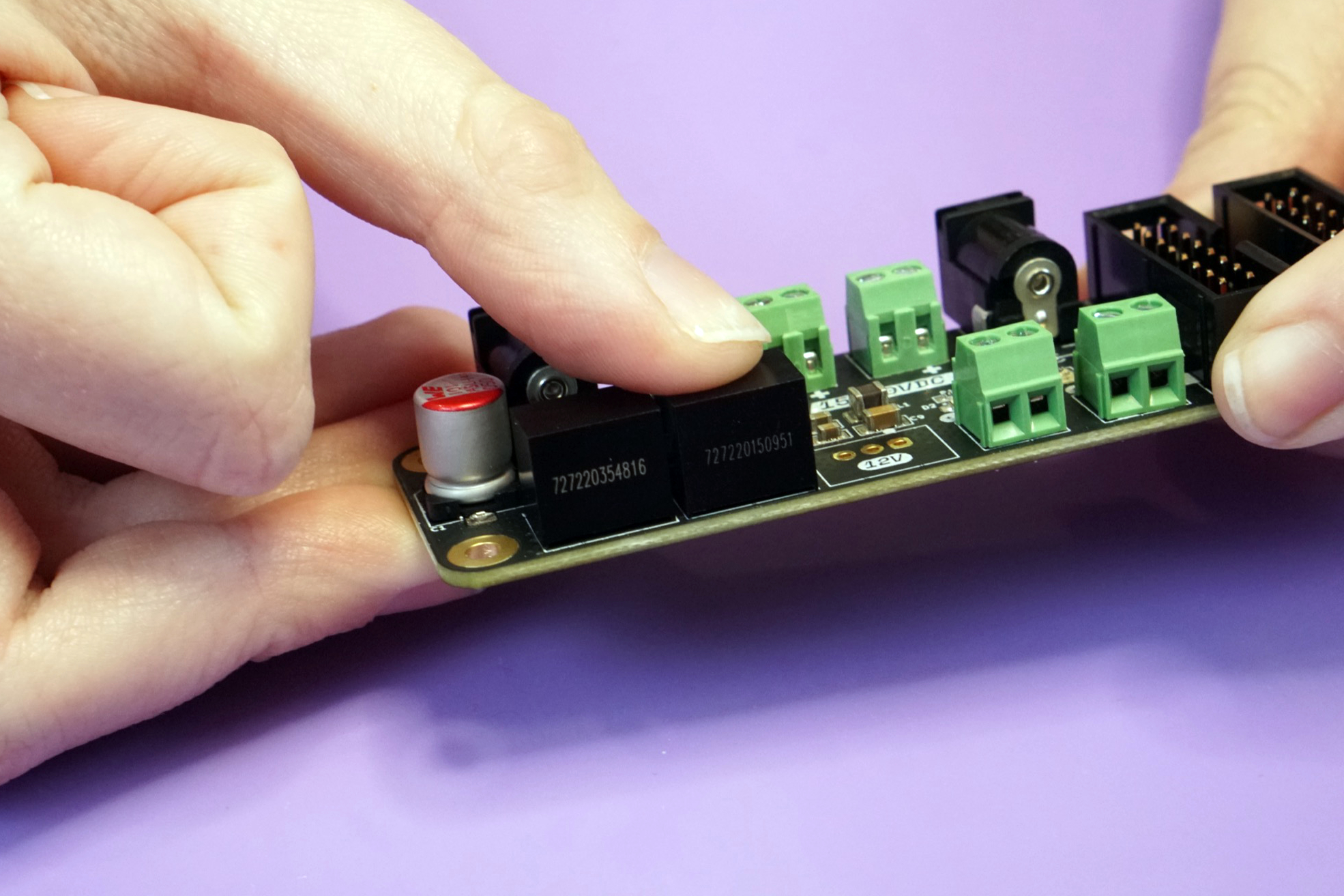
Repeat for the two 12V converters. They go into spots adjacent to the 5V converter marked 12V. Again, make sure that they are oriented to match up with the corresponding white rectangle on the board.
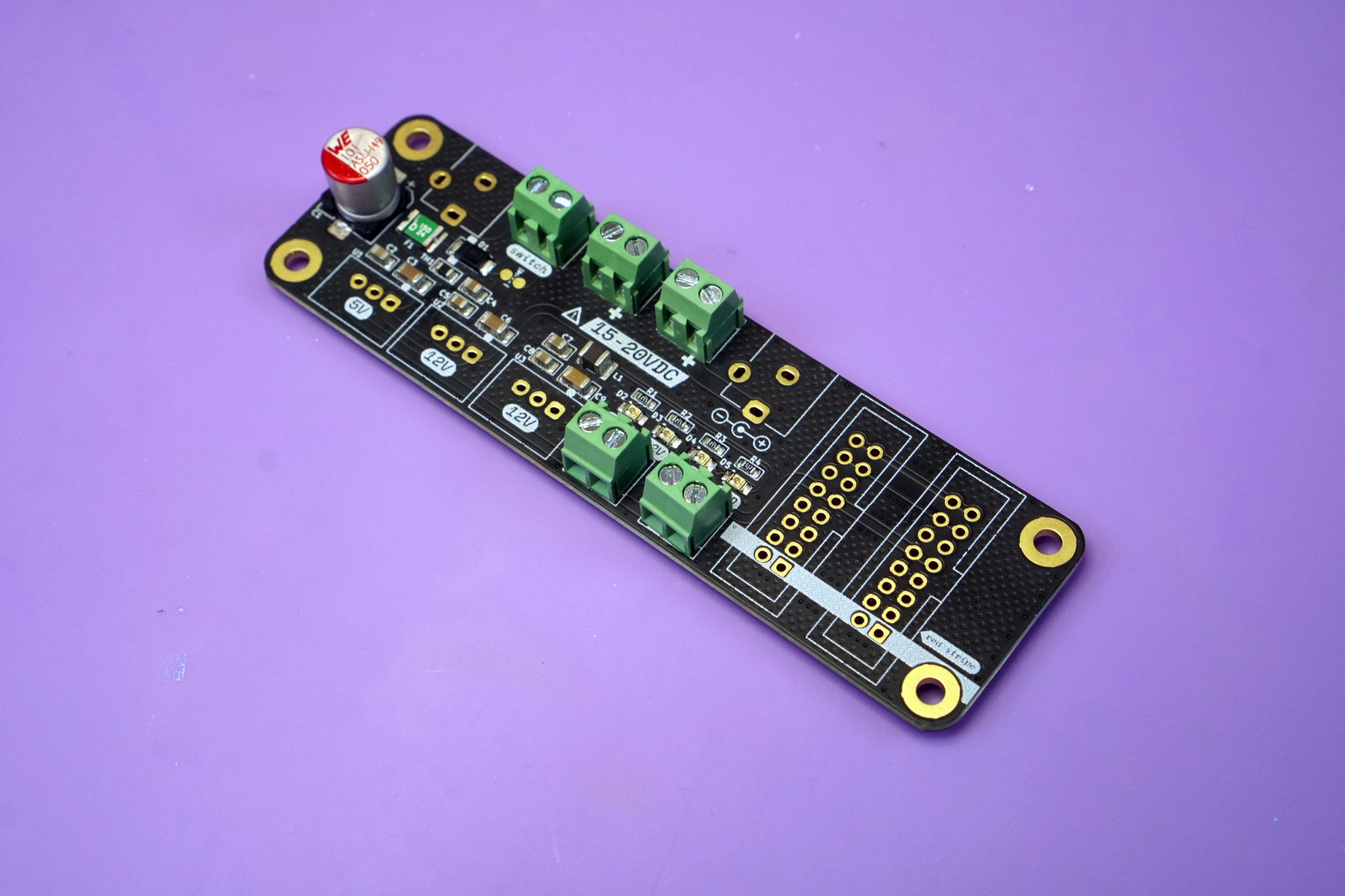
You're all done! If you have a busboard kit or a front entry kit, continue reading. If not, hop down to the end for some useful links.
Busboard#
The busboard kit adds six additional power headers to your Micronova.
Your busboard kit should contain the following items. If any are missing please email us at support@winterbloom.com.
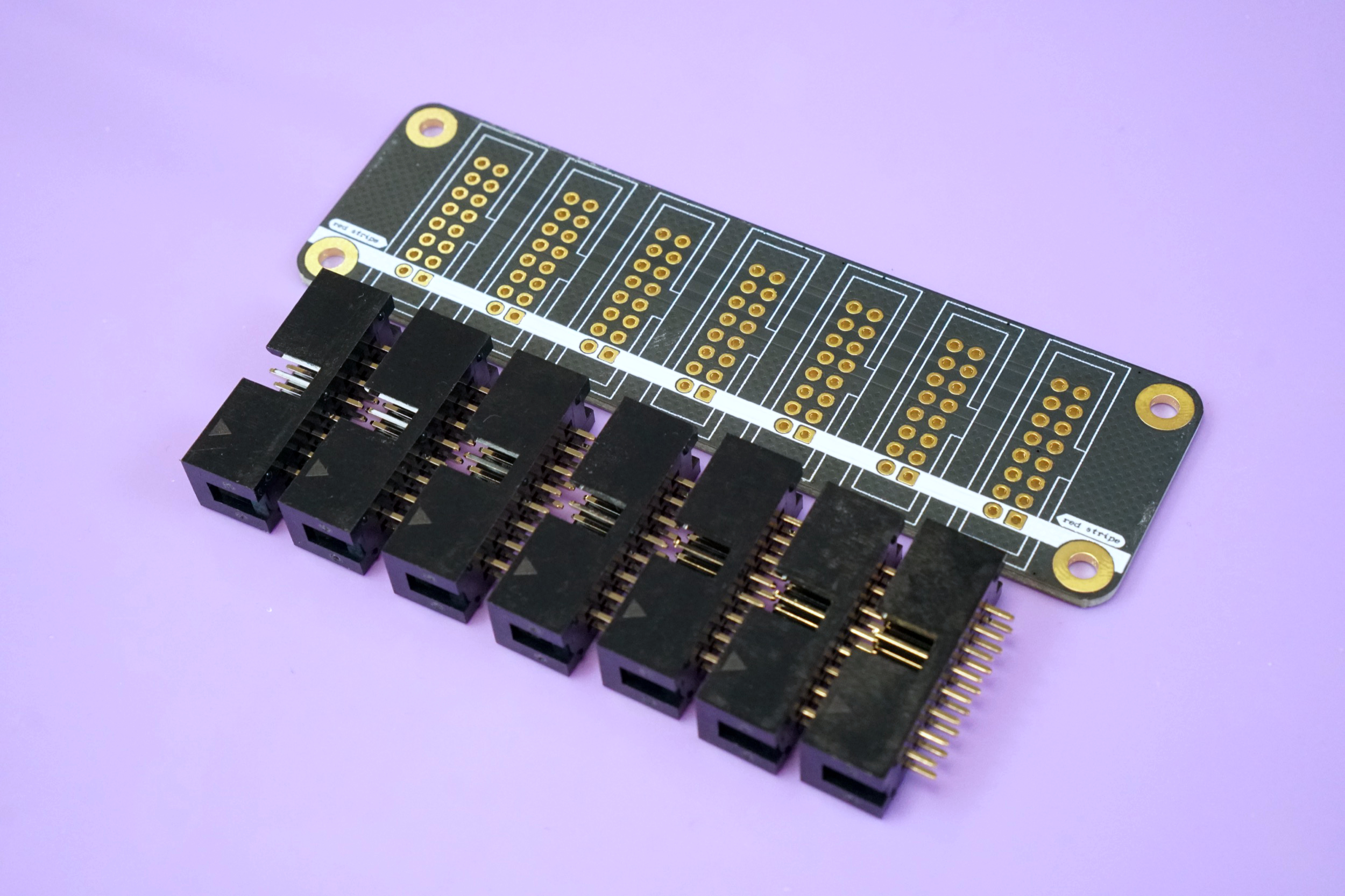
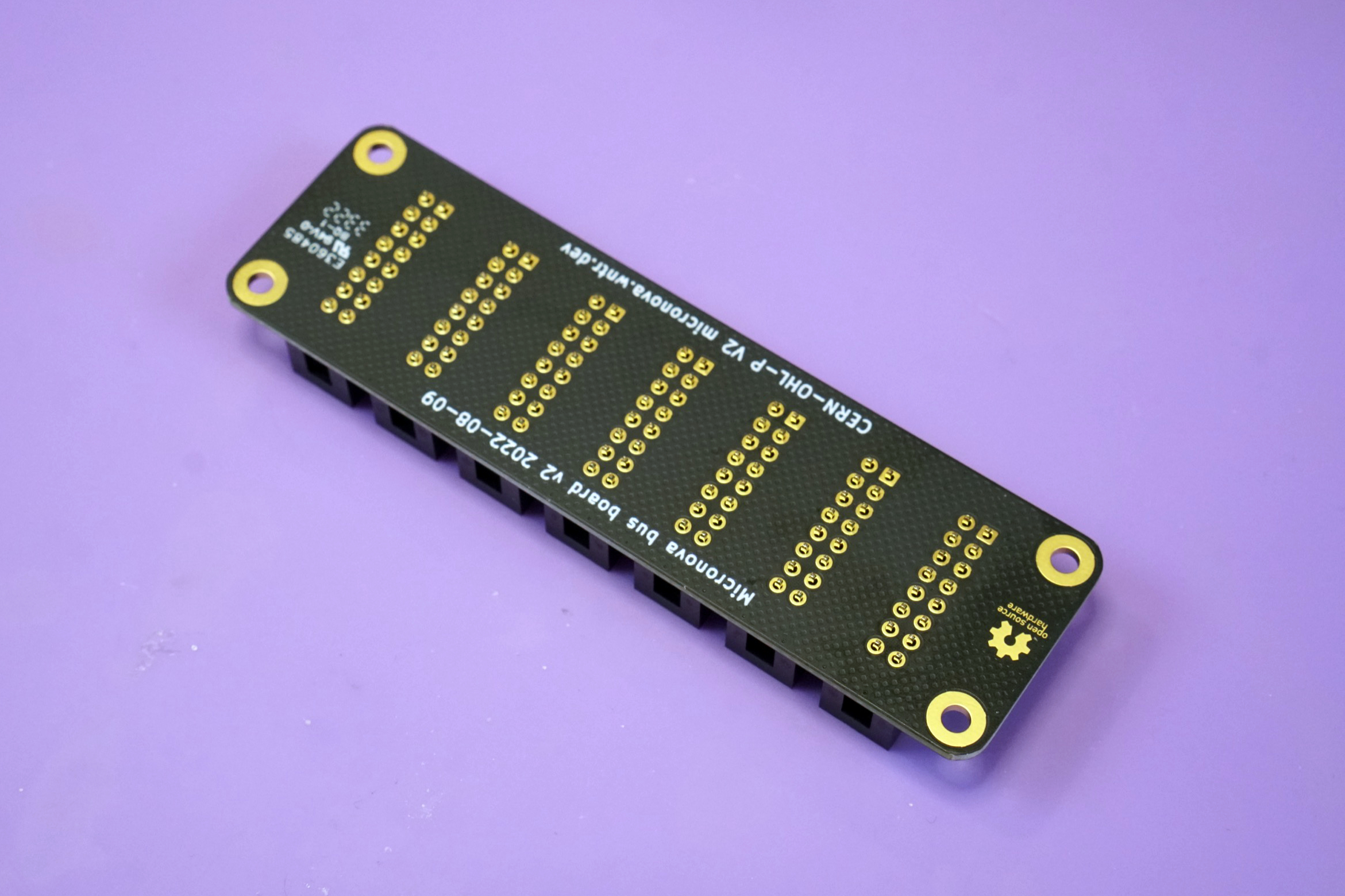
- (1) Busboard PCB
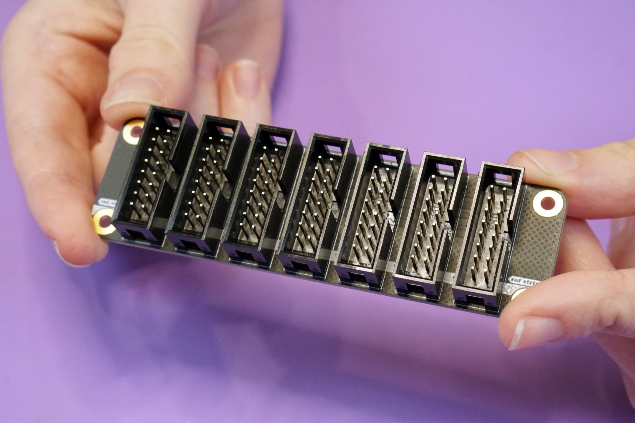
- (7) 2x8 pin shielded IDC headers
- (1) 16 pin to 16 pin IDC cable (not pictured)
Assembling the busboard kit is fairly straightforward. Start by placing all seven IDC headers on the front side of the board, making sure to align the notch in the header's shield with the drawing on the board. The board is designed to hold on to these headers tightly, so you might have to give a little pressure to push them all the way in.
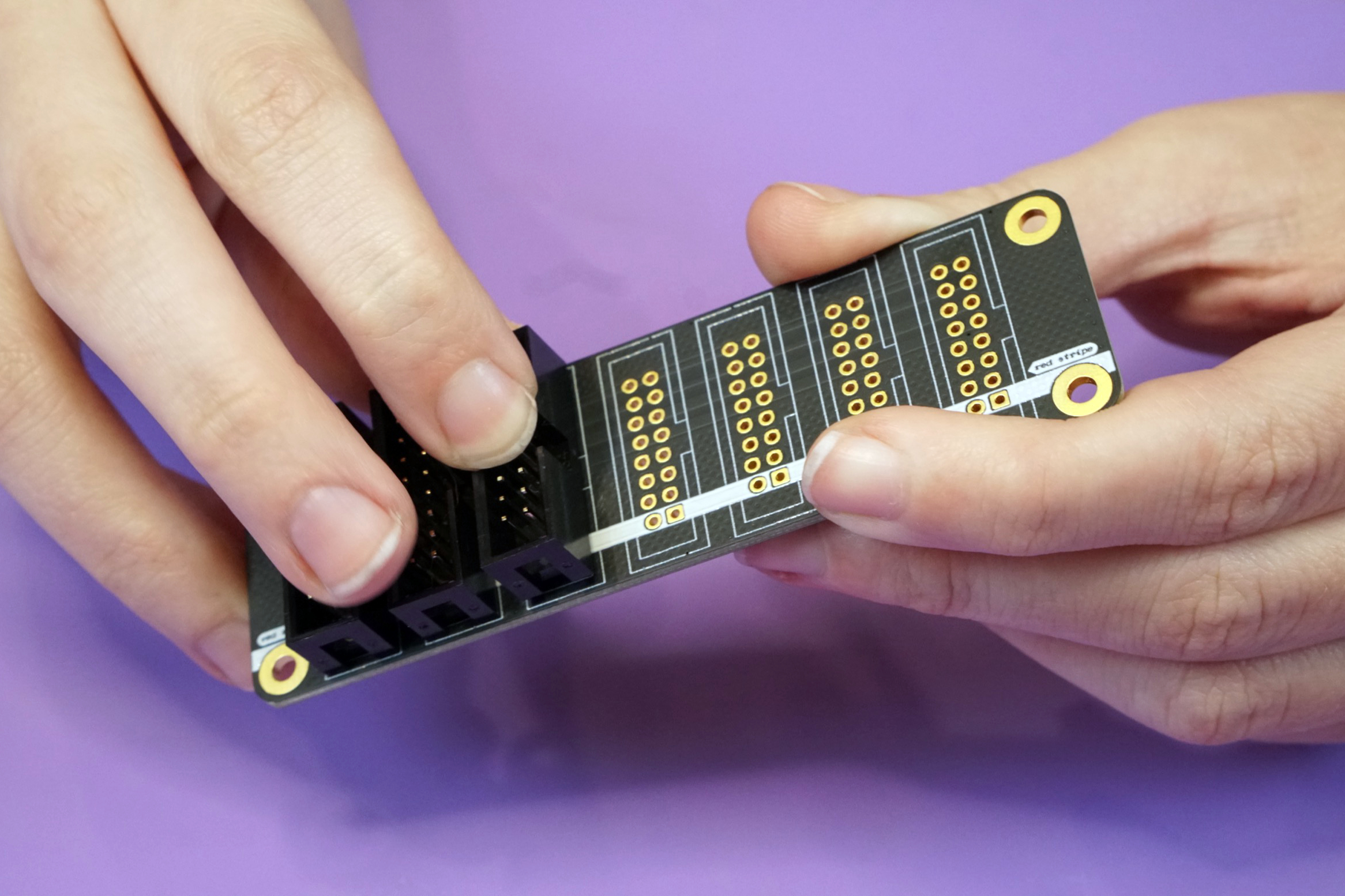
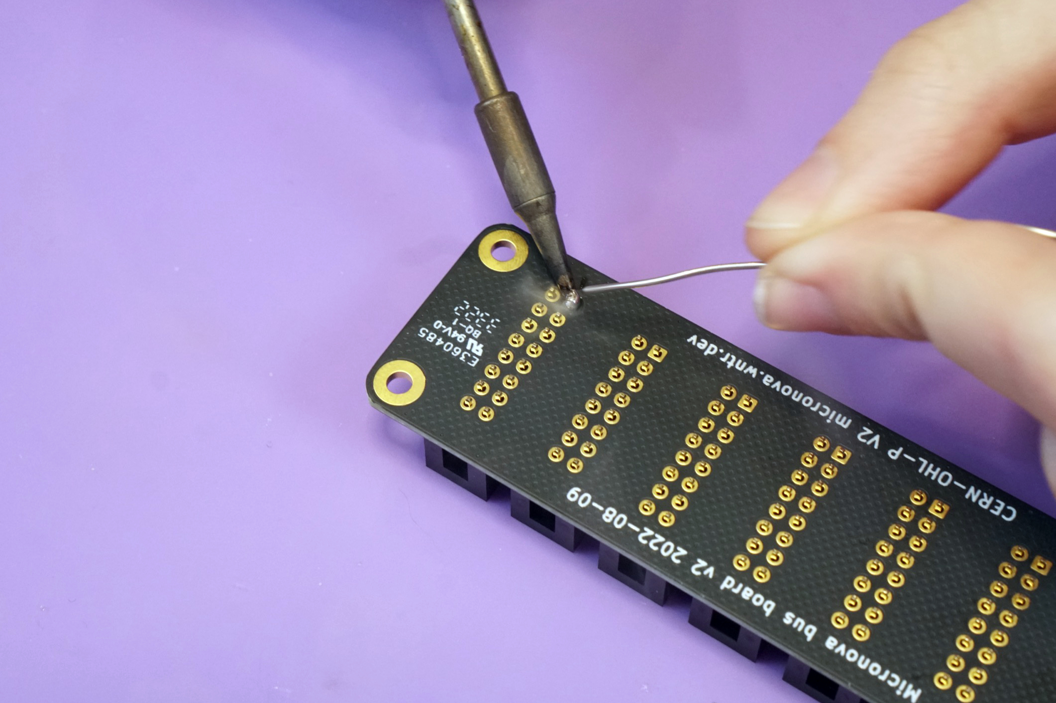
Flip the board over and solder one pin on each header to tack them into place.
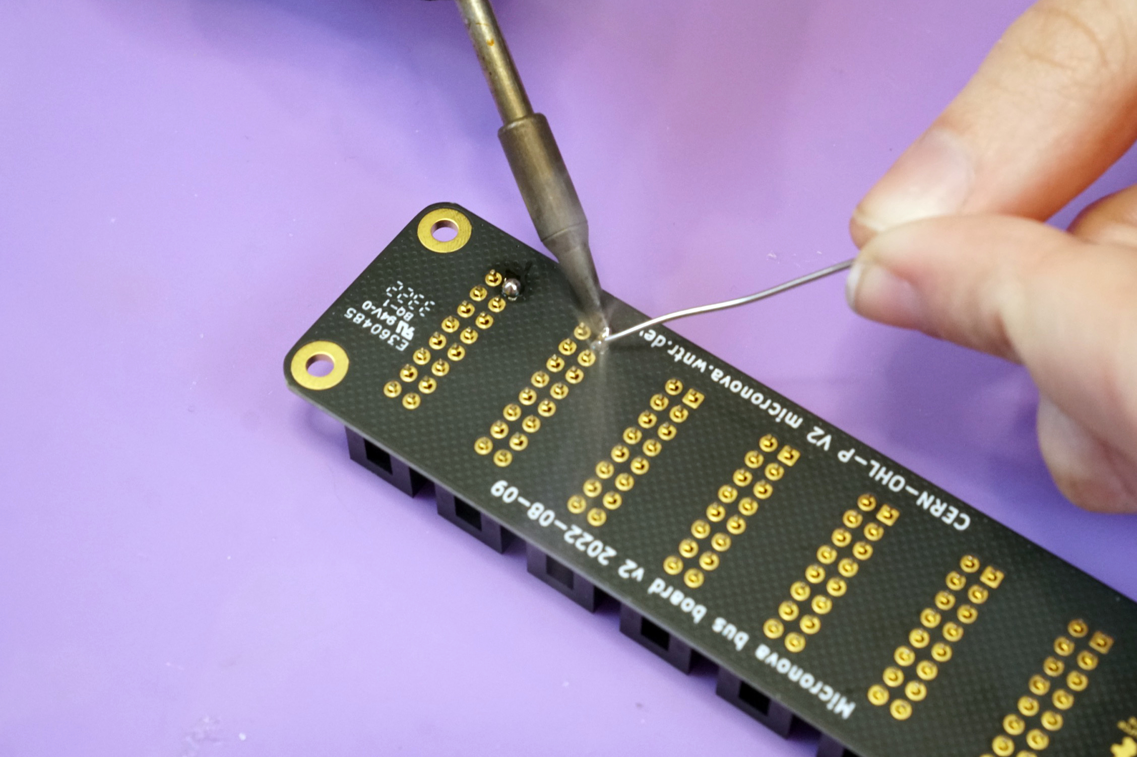
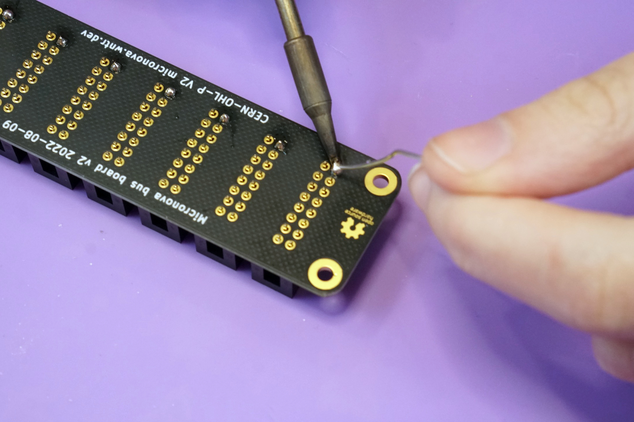
Make sure that the headers are all flush against the board and adjust if needed by re-heating the solder joints. Once you're sure they're all flush, solder them all in to place.
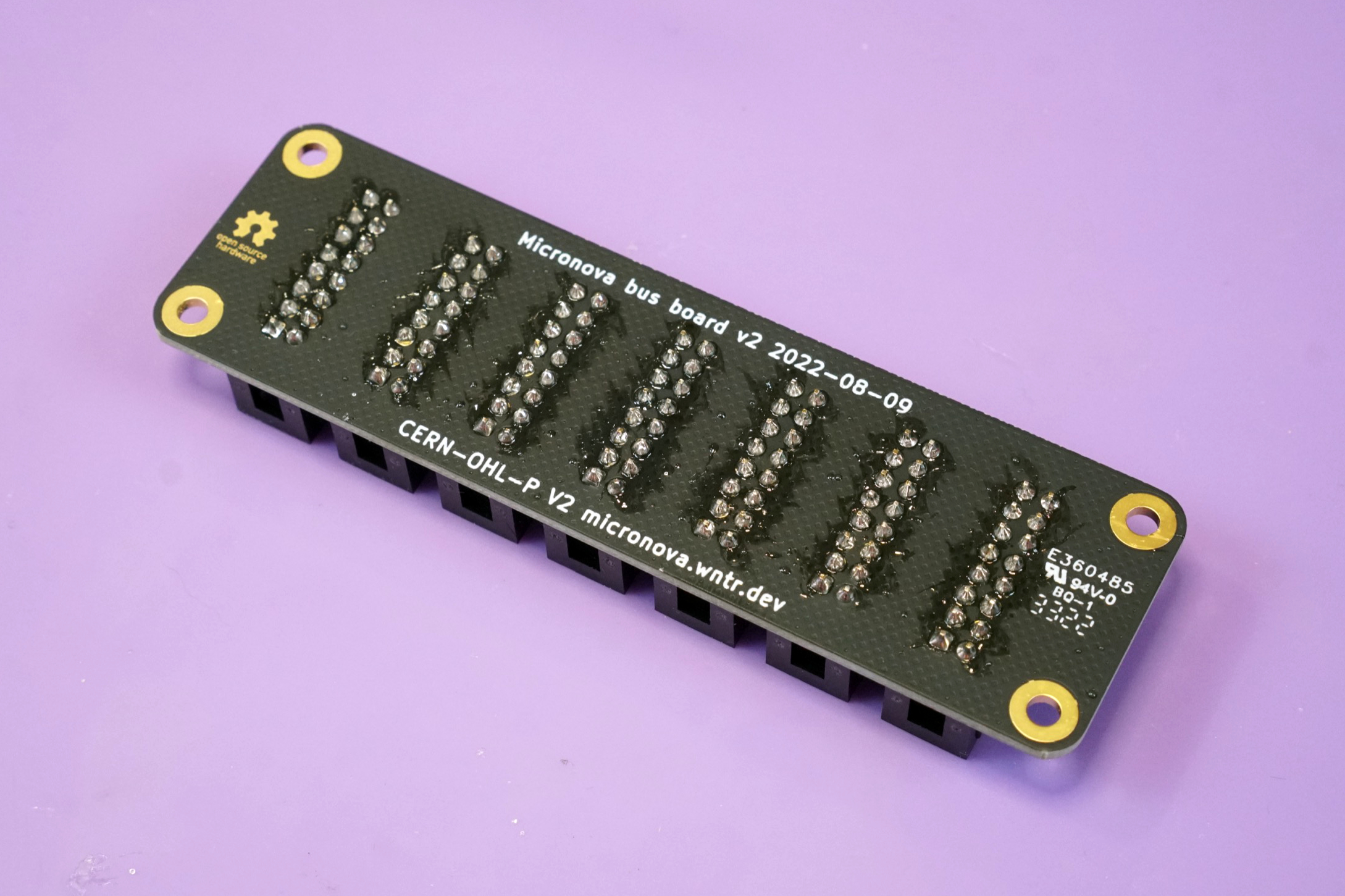
That's it! 🙂
Front entry kit#
The front entry kit lets you power your Micronova via a 4hp panel in your rack.
Your front entry kit should contain the following items. If any are missing please email us at support@winterbloom.com.
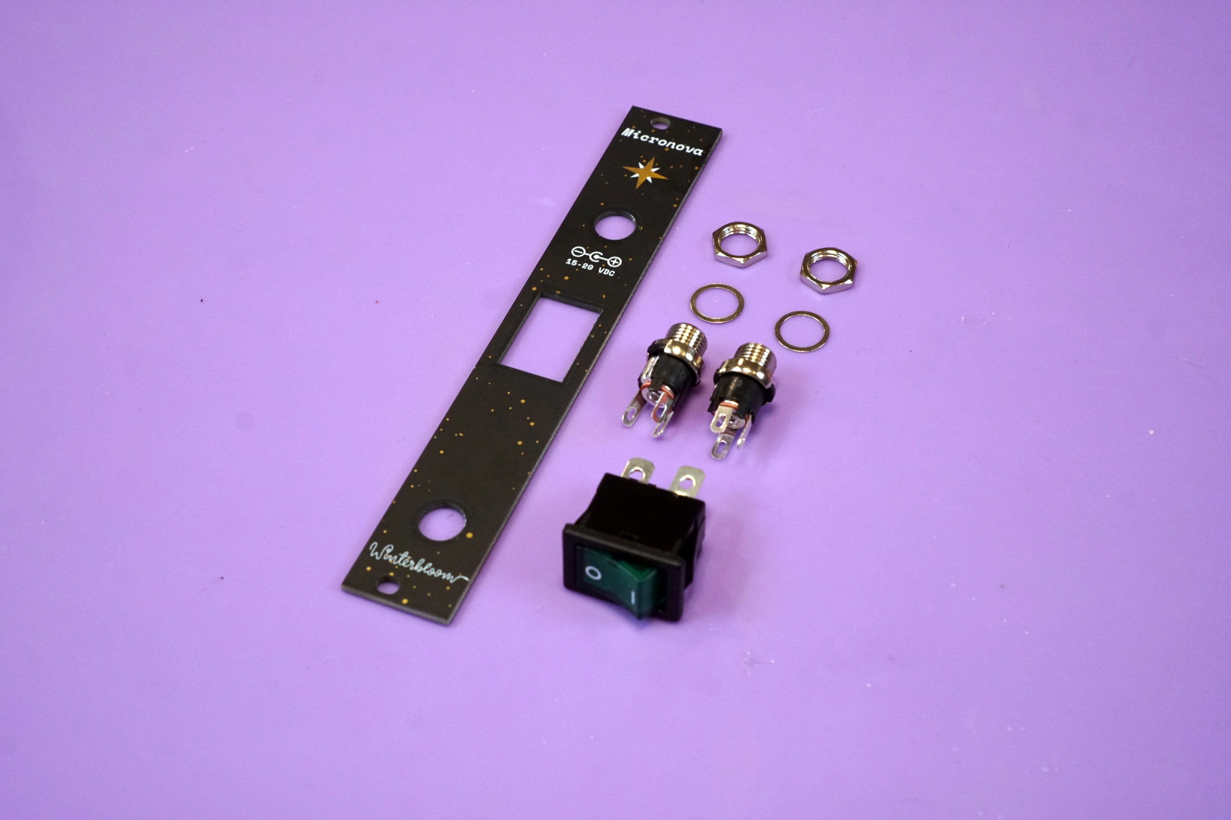
- (1) Front entry panel
- (2) Panel mount DC barrel jacks, including washers and nuts
- (1) Rocker switch
- (2) M3x6 mounting screws (not pictured)
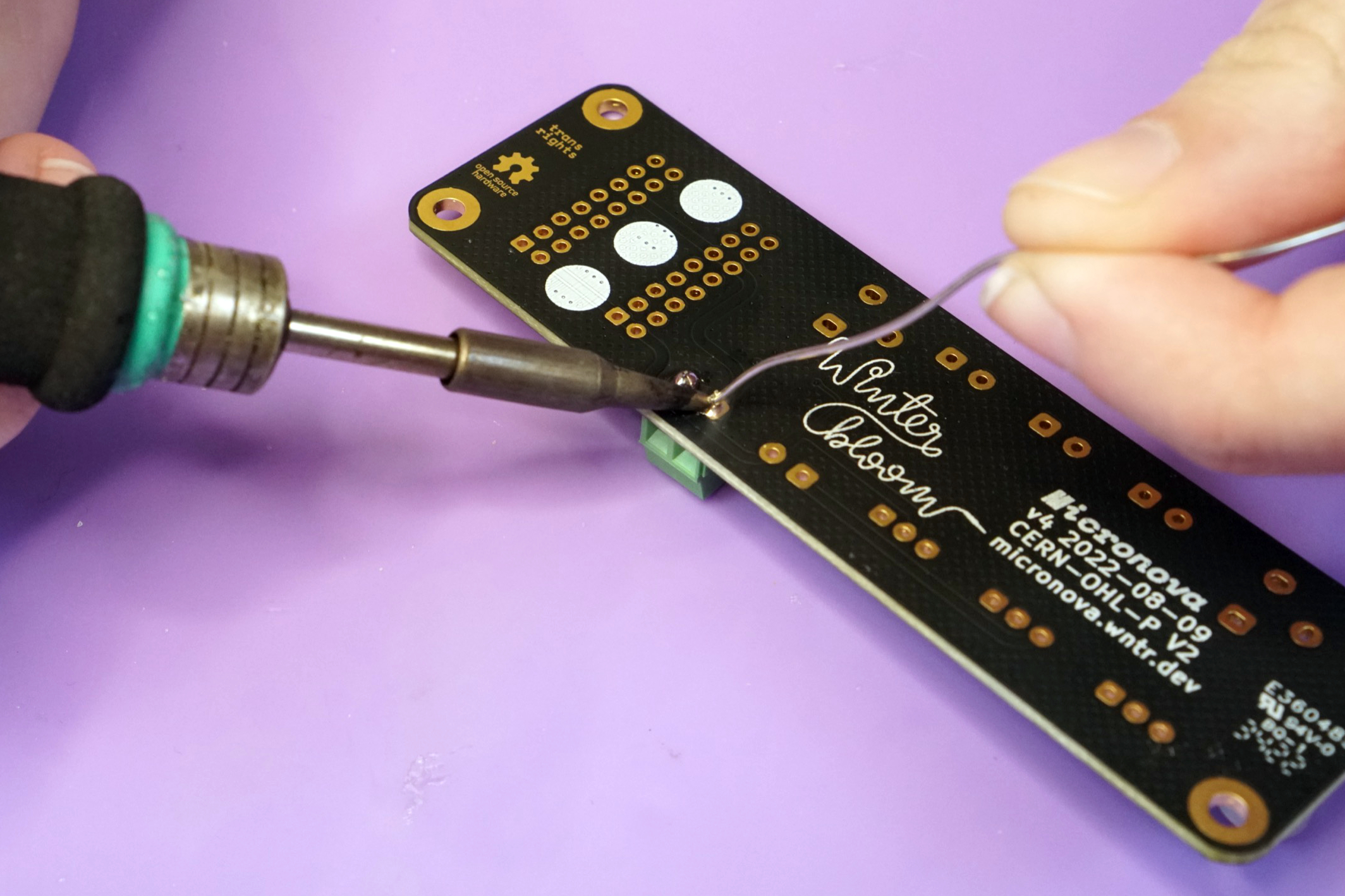
You will need hook up wire to assemble this module. We recommend 20 or 22 AWG stranded wire in red and black.
The first step is to prepare four 13cm (5") lengths of wire- two red, and two black. Strip the sleeve 1cm on both ends.
You also need two lengths of wire that will connect from the front panel to the Micronova board inside your case. Make sure you have enough length to reach and strip the sleeve 1cm on both ends.
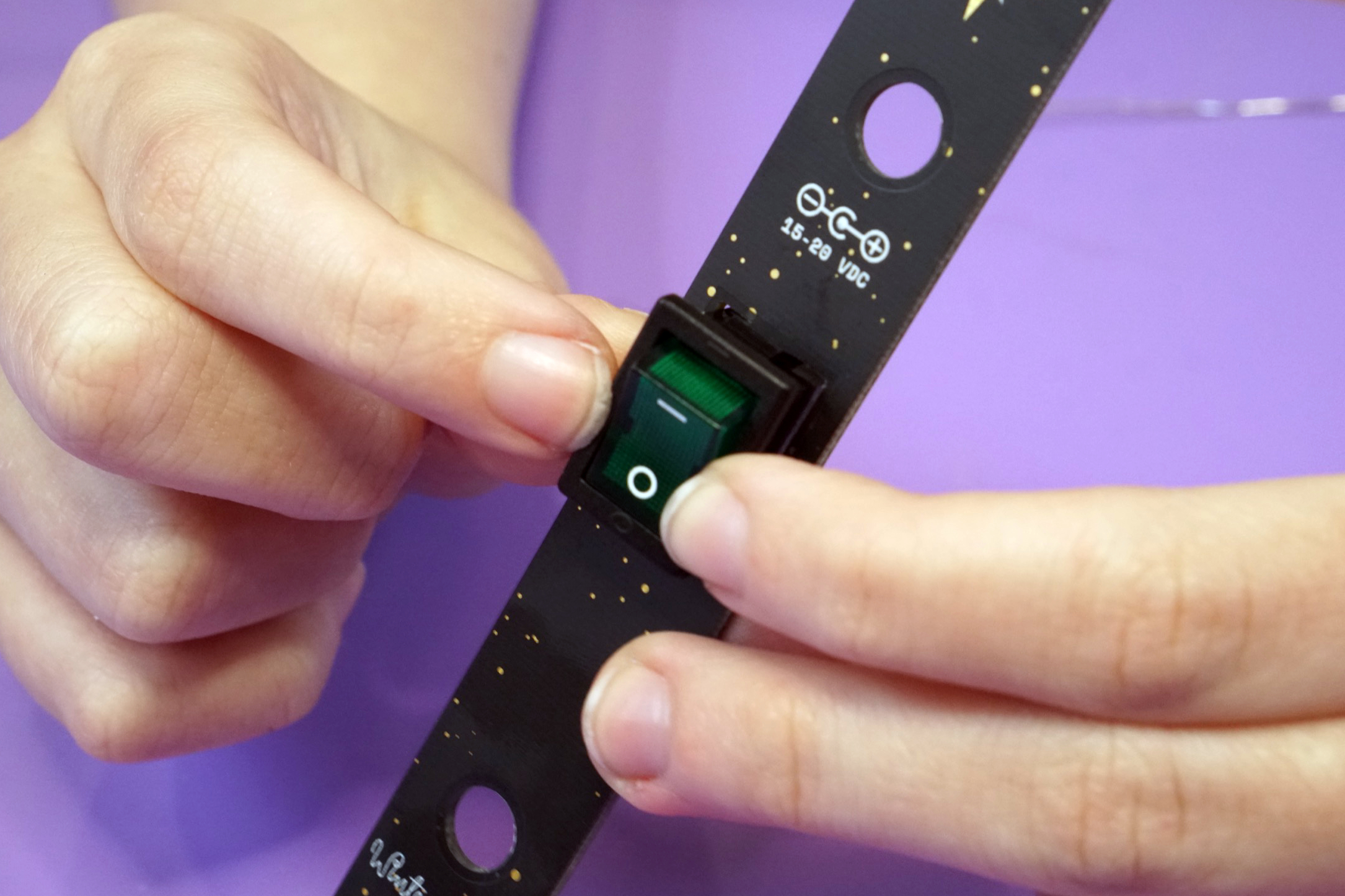
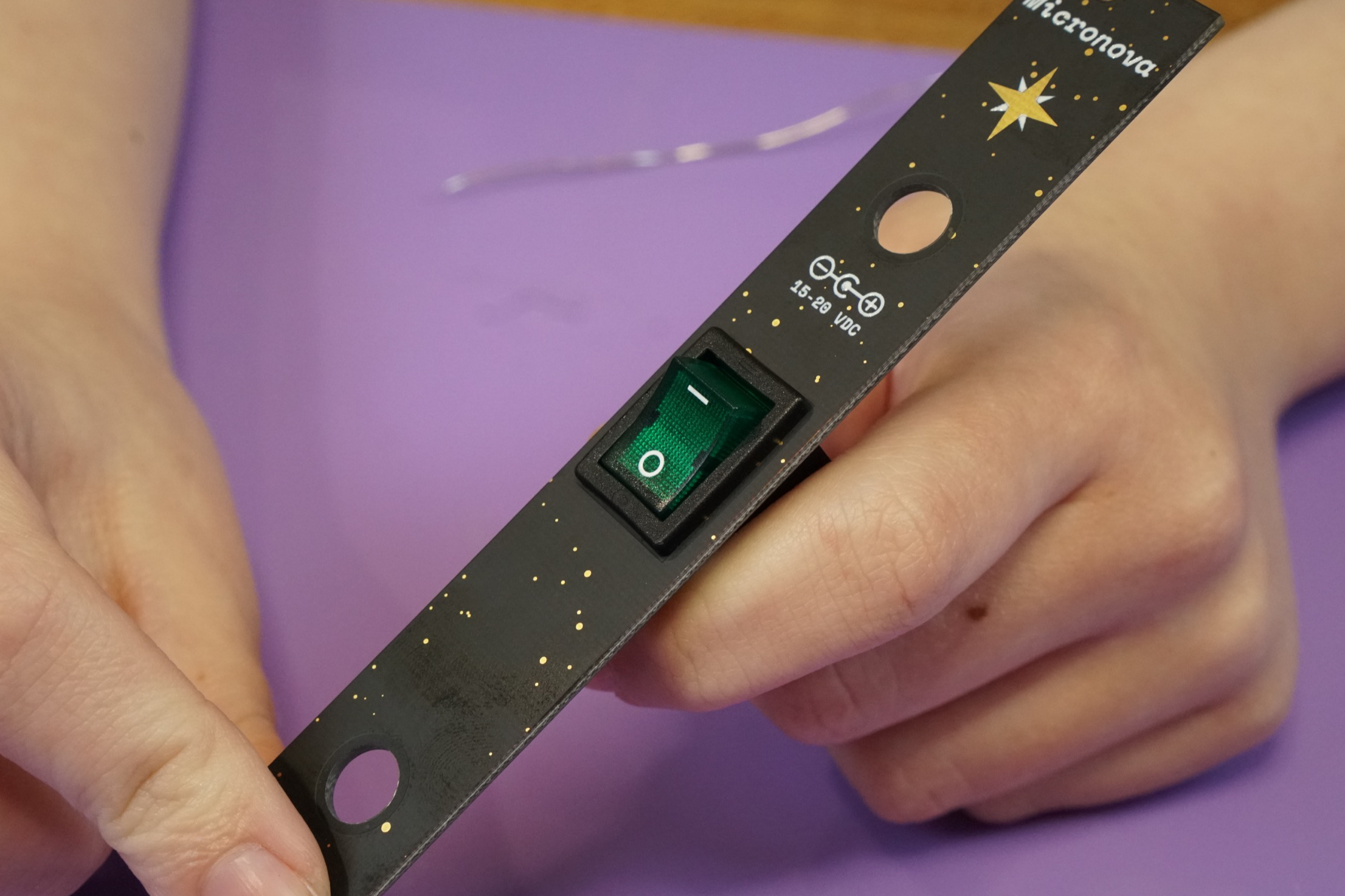
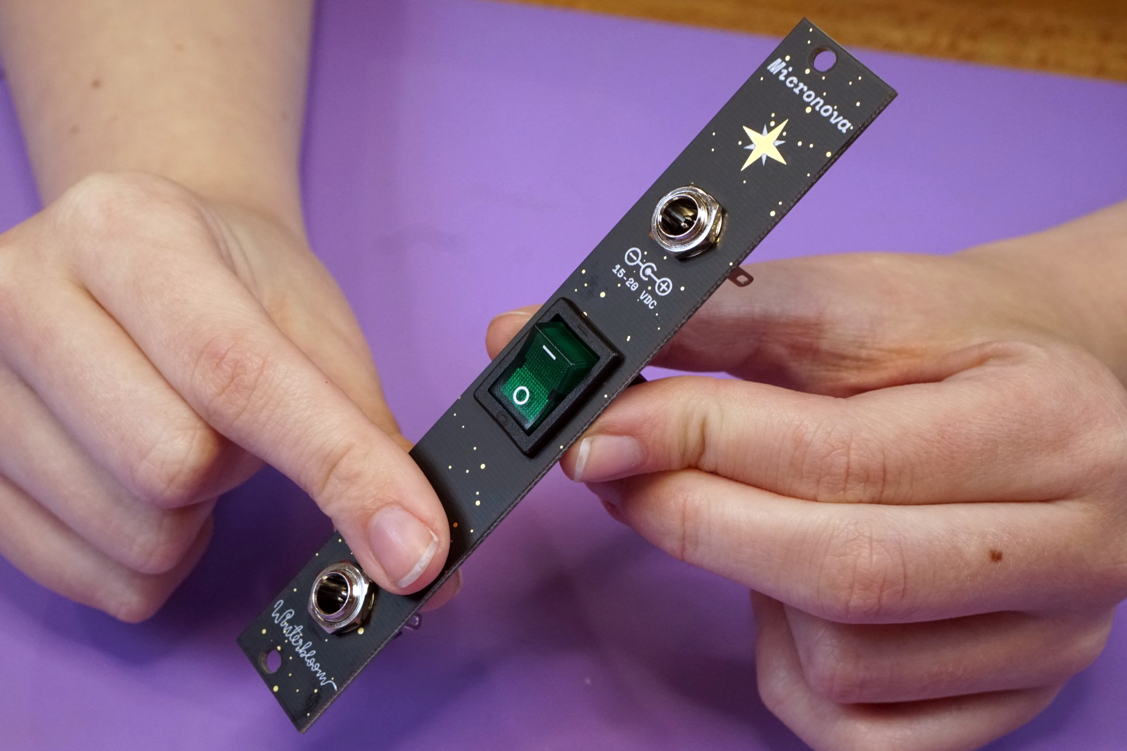
Mount the switch in the panel, making sure that the - is facing upwards. The panel's switch cutout has a very tight fit, so you may have to compress the plastic springs on the switch to get it to snap into place.
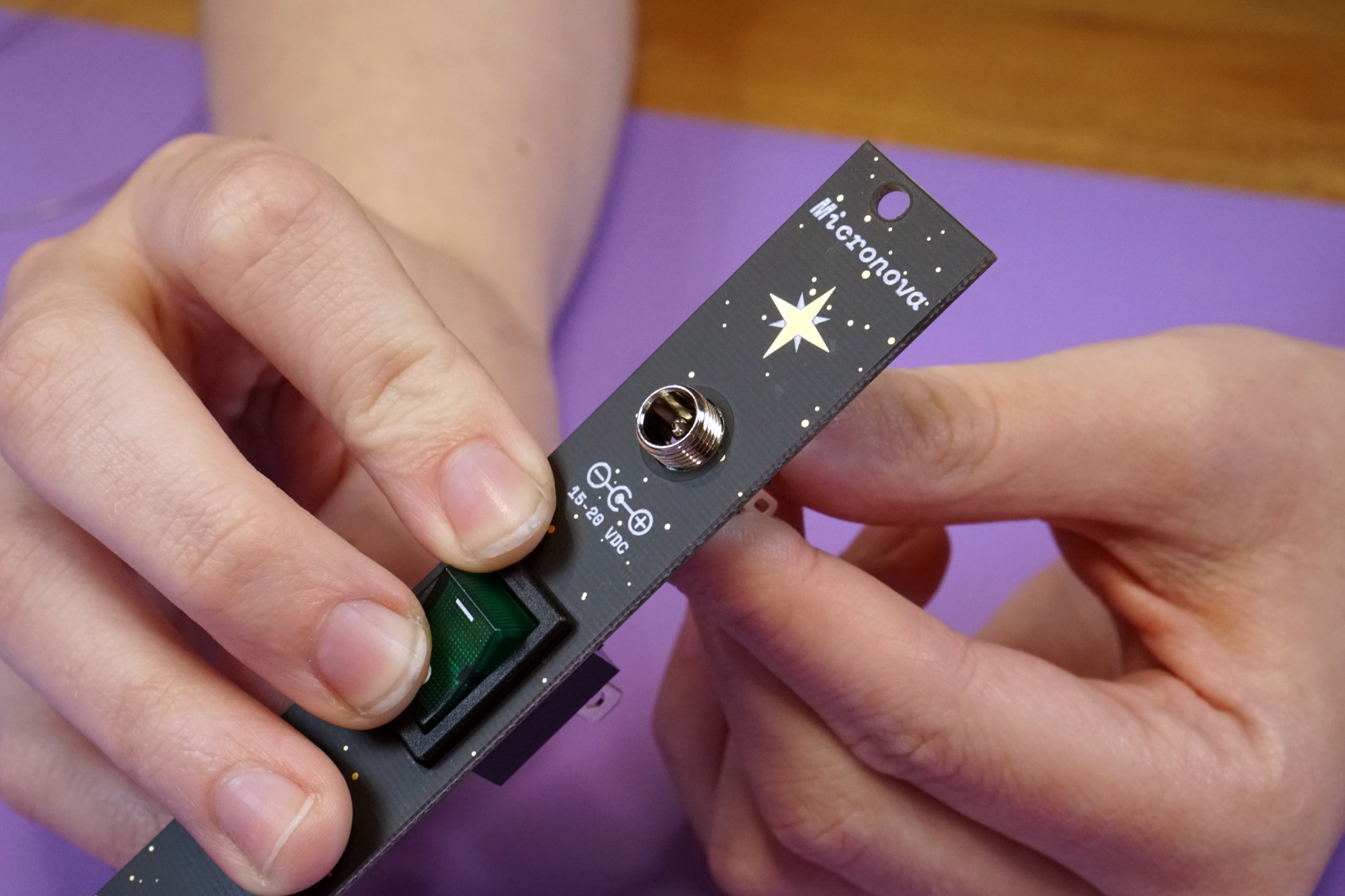
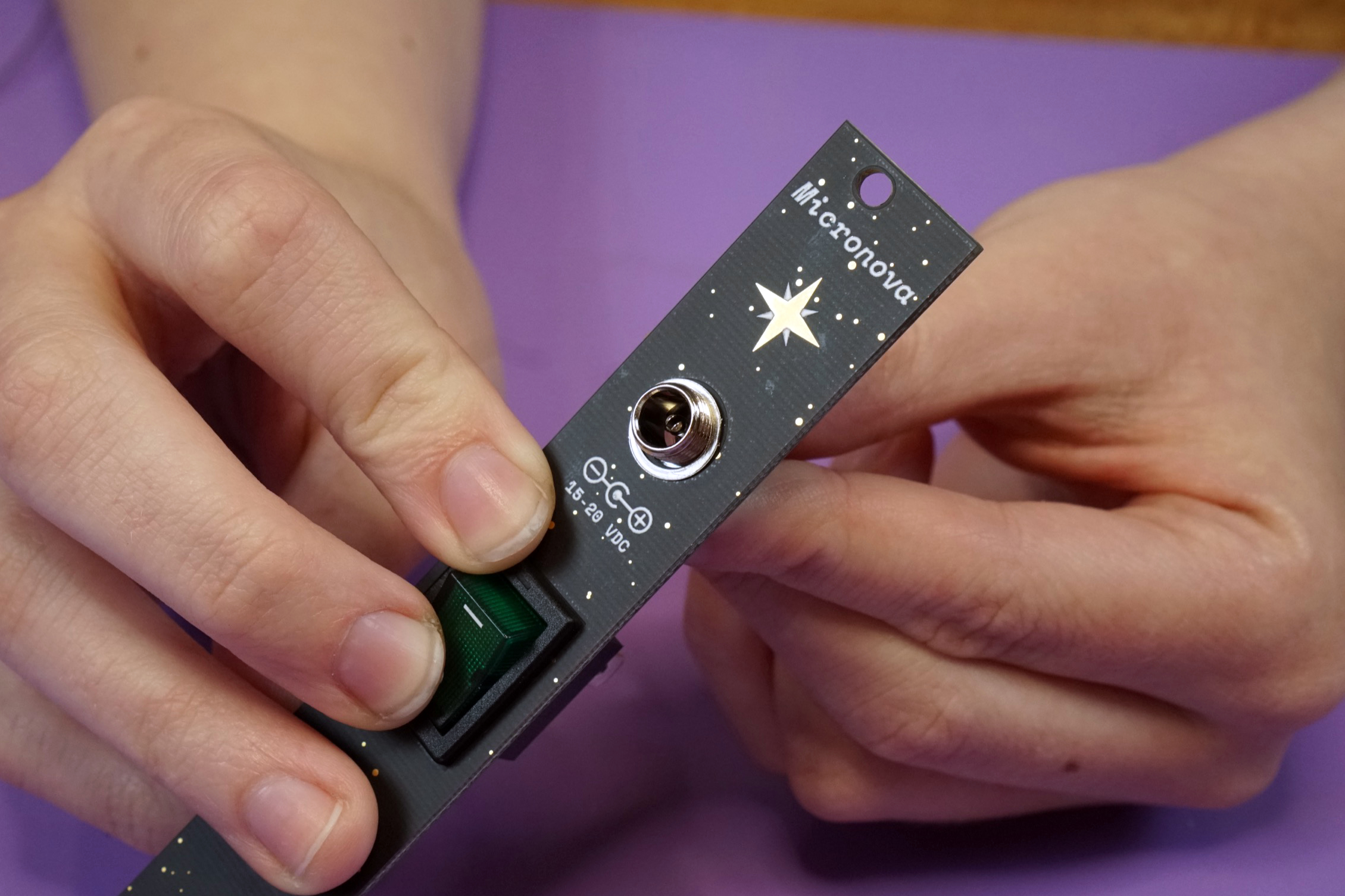
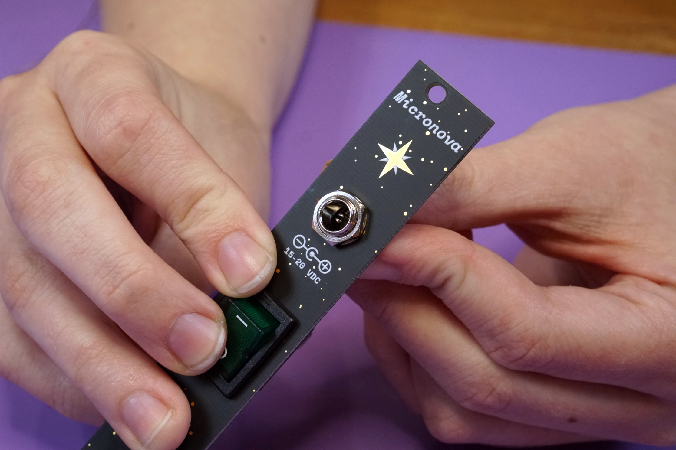
Mount the two DC barrel jacks to the panel, placing the washer and nut onto the jack from the front side of the panel.
Wire the jacks and switch together as shown below, being care to wire the the correct leads on the barrel jacks.

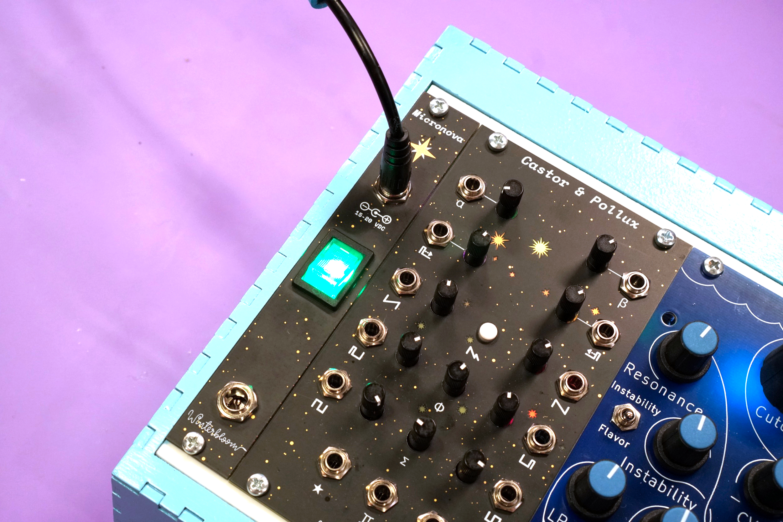
With everything wired up, give it a quick test by plugging in a power cable and making sure that the switch illuminates when switched on. If it does not illuminate or if it stays illuminated even when off, double-check your wiring before continuing.
If everything checks out, mount the panel in your rack.
Run the power wires to your Micronova and use the screw terminals to connect them.

All done#
Congratulations! You've finished your very own Micronova!
Now that it's all put together go check out the User's Guide and please show us your work by tweeting at @wntrblm or tagging @wntrblm in your instagram post.